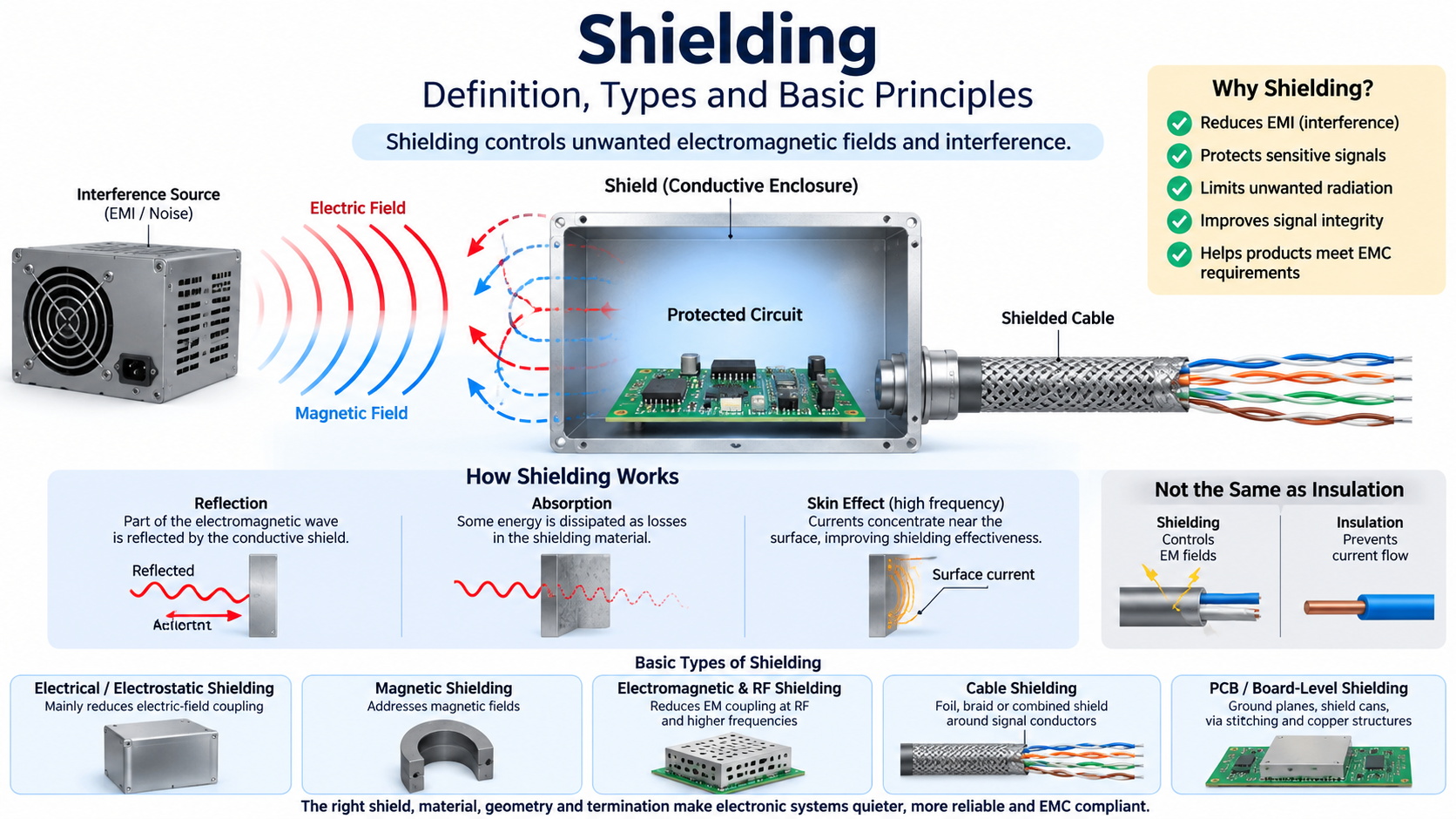
Shielding
is a technique used in electrical and electronic systems to control unwanted electromagnetic coupling. A shield can reduce the amount of electromagnetic energy entering a circuit, prevent energy generated by a circuit from escaping into its surroundings, or provide a controlled path for interference currents. Shielding is therefore an important part of EMI control, signal integrity, cable design, PCB design, instrumentation, and electromagnetic compatibility (EMC).
The basic idea is simple: place a conductive or, in some applications, magnetic material between a sensitive circuit and an interfering electromagnetic field. In practice, however, effective shielding depends on frequency, field type, material properties, geometry, openings, seams, grounding or bonding, and the way the shield is terminated.
Shielding should also not be confused with insulation. Electrical insulation prevents unwanted current from flowing between conductors, whereas shielding controls electromagnetic fields and interference. A cable can therefore have excellent insulation while having little or no electromagnetic shielding.
What Is Shielding in Electrical Systems?
In an electrical system, shielding means creating a barrier or controlled electromagnetic boundary around a conductor, circuit, component, cable, enclosure, or sensitive region. The purpose is to alter the path by which electromagnetic energy couples between a source and a victim circuit.
For example, a sensitive sensor cable routed beside a switching power converter can pick up unwanted interference through electric and magnetic fields. Adding an appropriate shield around the cable can reduce this coupling. Likewise, a metal enclosure around an electronic circuit can limit both the radiation emitted by the circuit and the external fields reaching the circuitry inside.

Shielding is therefore best understood as part of a larger electromagnetic-control strategy rather than as a simple metal covering.
Why Is Shielding Used?
Electronic systems can both receive and produce electromagnetic interference. A high-speed digital circuit, switching regulator, motor controller, or communication interface may generate rapidly changing electric and magnetic fields. Those fields can couple into nearby circuits and cables. Conversely, an external electromagnetic source can couple into a sensitive receiver or measurement circuit.
Shielding is used to reduce these unwanted interactions. Typical objectives include reducing radiated interference, protecting sensitive signals, limiting RF coupling, improving measurement accuracy, reducing crosstalk, and helping equipment meet EMC requirements.
It is important to recognize that shielding does not operate independently of the rest of the circuit. Twisting, differential signaling, grounding, bonding, filtering, physical separation, and PCB layout can all influence the final result. A shield that is poorly designed or improperly terminated may provide much less protection than expected.
Basic Types of Shielding
The word shielding covers several different engineering approaches. The appropriate method depends primarily on the type and frequency of the interfering electromagnetic field.
Electrical or Electrostatic Shielding
Electrical shielding, often called electrostatic shielding, is primarily concerned with electric fields. A conductive barrier redistributes induced charge and can provide a path that prevents the electric field from strongly coupling into the protected circuit.
Conductive enclosures, cable screens, conductive foil layers, and metal shields are common examples. The effectiveness depends on continuity, geometry, openings, and the electrical connection of the shield.
This type of shielding is especially relevant when capacitive or electric-field coupling is the dominant interference mechanism.
Magnetic Shielding
Magnetic shielding addresses magnetic fields and is more difficult than ordinary electric-field shielding, particularly at low frequencies. The material and geometry must be selected according to the field frequency and strength.
High-permeability materials may be used when redirecting magnetic flux is more effective than relying on ordinary conductive shielding. At higher frequencies, conductive materials can also provide substantial attenuation because changing magnetic fields induce currents that oppose the incident field.
Electromagnetic and RF Shielding
Electromagnetic shielding is the broader concept of reducing electromagnetic-field coupling into or out of an electronic system. At radio and high frequencies, conductive shields can provide attenuation through mechanisms including reflection and absorption.
RF shielding is a closely related application focused on radio-frequency energy. RF shields are used in electronic enclosures, communication equipment, sensitive measurement instruments, wireless modules, cable assemblies, and printed circuit boards.
Cable Shielding
Cable shielding places a conductive layer around one or more signal conductors. Depending on the construction, the shield may be a foil, braid, combination of foil and braid, or another conductive structure.
Cable shielding can reduce the coupling of external interference into the cable and can also reduce electromagnetic radiation generated by the cable itself. This makes it particularly important in instrumentation, industrial communication, high-speed data links, and electrically noisy environments.
Different cable constructions require different termination methods. Topics such as foil shields, braided shields, drain wires, shield pigtails, and shield termination are therefore separate engineering subjects rather than interchangeable terms.
PCB and Board-Level Shielding
Shielding is also used directly on printed circuit boards. Engineers may use ground planes, via stitching, shield cans, conductive barriers, controlled return paths, and carefully designed copper structures to reduce electromagnetic coupling.
PCB shielding is closely related to signal integrity and EMC design because high-speed traces can both radiate and receive interference. The effectiveness of a PCB shield depends not only on the material but also on current return paths, apertures, layer structure, trace geometry, and enclosure bonding.
How Does Shielding Work?
There is no single mechanism that explains every shield. The dominant behavior depends on the electromagnetic environment and the construction of the shield.
A conductive shield can reflect a portion of an incident electromagnetic field. Some of the electromagnetic energy that enters the shielding material is dissipated through losses in the material, producing absorption. At sufficiently high frequencies, the skin effect concentrates induced currents near the surface of a conductor, which can further influence shielding performance.
Real shields also contain seams, openings, connector interfaces, and cable entry points. These discontinuities can become significant leakage paths, particularly as frequency increases. Consequently, a shield’s performance depends on the complete physical structure rather than simply the conductivity of the material.
Shielding Is Not the Same as Grounding
A shield and a ground connection perform different functions. The shield is the electromagnetic barrier or conductive boundary; grounding or bonding determines how that conductive structure is electrically referenced or connected within the system.
Depending on the application, a shield may be connected to signal reference, chassis, protective earth, or another defined bonding point. The correct arrangement depends on the system architecture, frequency, safety requirements, and EMC objectives.
This is why statements such as “just connect the shield to ground” are incomplete engineering advice. Shield termination and bonding deserve separate treatment because the best connection for a low-frequency system is not automatically the best high-frequency solution.
Common Shielding Materials
Common shielding materials include copper, aluminum, steel, conductive fabrics, conductive coatings, and specialized high-permeability magnetic materials. Material selection depends on the field type, frequency range, mechanical requirements, weight, corrosion resistance, manufacturing process, and required shielding effectiveness.
For cable applications, copper and aluminum are common conductive shielding materials. Copper offers high electrical conductivity and is widely used for braids and screens. Aluminum foil provides extensive surface coverage with very little material thickness. A combination of foil and braid can provide complementary mechanical and electrical properties.
Shielding, Twisting and Filtering Work Together
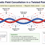
Shielding is only one tool for controlling interference. A well-designed communication system may combine several methods. Twisting reduces the effective coupling of a balanced pair, differential signaling rejects common-mode interference at the receiver, filtering attenuates unwanted frequency components, and shielding reduces electromagnetic coupling between the signal system and its surroundings.
For example, an Ethernet cable can use carefully controlled twisted-pair geometry to maintain balance while an additional conductive screen can provide protection against stronger electromagnetic environments. A PCB can use differential routing, a continuous reference plane, filtering, and a shielded enclosure simultaneously.
Shielding Topics Covered in This CircuitFeed Guide
Shielding is a broad engineering subject, so each specialized area should be studied separately rather than compressed into one general article. The following topics will expand the concepts introduced here.
- Electromagnetic Shielding — field physics, reflection, absorption, skin effect, and shielding effectiveness.
- EMI Shielding — applying shielding specifically to electromagnetic interference problems.
- Shielding Materials — copper, aluminum, steel, conductive coatings, and magnetic materials.
- Cable Shielding — foil, braid, combined shields, and cable construction.
- Drain Wire — electrical connection to conductive cable shields.
- Shield Pigtail — the electrical and high-frequency consequences of pigtail termination.
- Shield Termination — connector, chassis, bonding, and high-frequency termination techniques.
- PCB Shielding — ground planes, shield cans, via stitching, and board-level EMI control.
These specialized articles should be treated as connected parts of one engineering subject. The present page establishes the vocabulary and basic classification; the individual articles provide the detailed mathematical analysis, construction methods, design trade-offs, and practical examples.
The Basic Idea to Remember
Shielding controls electromagnetic coupling. The shield may protect a circuit from external interference, contain electromagnetic energy produced by the circuit, or both. The correct shield depends on the field type, frequency, material, geometry, and termination method.
Once this basic idea is understood, terms such as electromagnetic shielding, EMI shielding, cable shielding, foil shield, braided shield, drain wire, pigtail, and PCB shielding become easier to distinguish. They are not separate definitions of the same thing; they describe different levels of the same engineering problem.