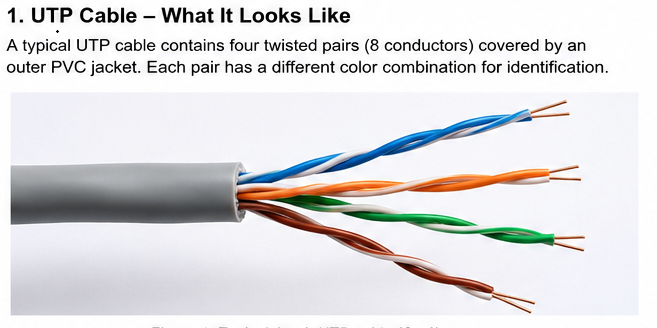
UTP cable stands for Unshielded Twisted Pair. It is a cable made from insulated conductors arranged as twisted pairs, but without a separate metallic shield around the cable or around the individual pairs. UTP is one of the most widely used balanced-cable constructions for communication, networking, telephone systems, instrumentation, and other electrical signal applications.
The word unshielded is important, but it is often misunderstood. UTP does not mean that the wires are unprotected, and it certainly does not mean untwisted pair. The conductors are deliberately twisted. What is absent is the additional conductive shield used in shielded cable constructions.
This distinction becomes especially important when comparing UTP with STP, FTP, and S/FTP cables, or when trying to understand why a cable without a metallic shield can still reject a surprising amount of electromagnetic interference.
For the electromagnetic principles behind twisting itself, see the CircuitFeed guide on twisted-pair cable, differential signaling and EMI reduction.
What Does UTP Mean?
UTP means Unshielded Twisted Pair. The term describes the physical construction of the cable rather than a particular data rate or Ethernet category.
The basic structure is straightforward: two insulated conductors are twisted together to form one balanced pair. A communication cable may contain one pair, several pairs, or many pairs depending on its application. In common networking cables, multiple twisted pairs are contained within a single outer jacket.
The term can therefore be separated into two parts:
- Twisted Pair describes the geometric arrangement of the conductors.
- Unshielded means there is no additional conductive screen around the cable or around the individual pair, depending on the standardized cable designation.
That second point is worth treating carefully because cable terminology can become ambiguous. Modern cabling systems use more precise designations such as U/UTP, F/UTP, U/FTP, and S/FTP to identify where shielding exists. UTP is commonly used as the short name for the unshielded construction.
UTP Does Not Mean Untwisted Pair
One of the easiest mistakes to make when reading the abbreviation is to mentally expand UTP as “untwisted pair.” That interpretation is incorrect. UTP means Unshielded Twisted Pair.
The difference is not merely grammatical. Twisting is one of the most important electrical features of the cable because it improves the symmetry of the pair and reduces electromagnetic coupling. An untwisted or poorly arranged pair can behave very differently, particularly when the conductors have unequal distances from nearby interference sources.
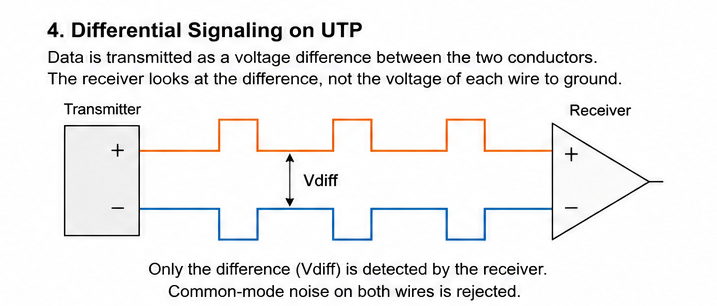
In a balanced differential system, the receiver ideally responds to the difference between the two conductor voltages:
V_{diff}=V_1-V_2If external interference couples equally into both conductors, the unwanted component can largely cancel at the differential receiver. The physical twisting of the pair helps the two conductors experience a more similar electromagnetic environment along the cable.
This is one of the central reasons why UTP can achieve good noise immunity even though it does not contain a metallic shield.
How Does UTP Cable Work?
The working principle of UTP is based on the combination of twisted geometry, balanced transmission, and differential signal detection. These mechanisms work together to reduce the effect of external electromagnetic interference and unwanted coupling between nearby circuits.
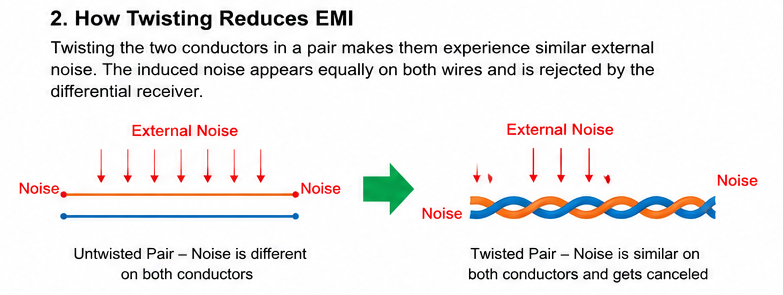
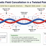
Consider two conductors carrying the forward and return components of a balanced signal. If they were kept apart as long, straight, parallel wires, the loop formed by the pair could expose a relatively large area to changing magnetic fields. That makes the pair more susceptible to induced voltage.
Twisting continuously changes which conductor occupies each physical position. One conductor is periodically closer to a particular external source while the other takes the corresponding position later along the cable. This geometric averaging reduces systematic coupling over the length of the cable.
For magnetic interference, the basic relationship comes from Faraday’s law. A changing magnetic flux through a conductive loop produces an induced electromotive force:
V_{induced}=-\frac{d\Phi}{dt}Twisting does not make the induced voltage mathematically disappear under every possible electromagnetic condition. Instead, it makes the coupling more symmetrical and causes successive sections of the pair to contribute with alternating spatial orientation, reducing the net interference seen by the complete transmission system.
UTP therefore achieves much of its interference rejection through geometry and balance rather than through a metallic barrier.
Why Can an Unshielded Cable Still Reject EMI?
The absence of a shield does not mean the cable has no defense against interference. It means that the cable relies primarily on the electrical properties of the twisted pair itself rather than on an additional conductive screen.
Suppose an external interference source produces approximately equal noise voltages on both conductors. Let the desired differential signal be V_s , and let the common noise appearing on the two conductors be V_n . The two conductor voltages can be represented conceptually as:
V_1=V_s+V_n
V_2=V_n
The receiver measures the difference:
V_{diff}=V_1-V_2V_{diff}=(V_s+V_n)-V_n=V_sIn this simplified ideal case, the common-mode interference cancels completely. Real cables are not perfectly symmetrical, so cancellation is never infinite. Differences in conductor geometry, termination, twist, nearby fields, connectors, and the receiver itself determine how much noise remains.
This is why UTP should not be described simply as “a wire with no shield.” It is a balanced transmission structure whose geometry is deliberately engineered to control electromagnetic coupling.
UTP and Signal Integrity
Signal integrity becomes increasingly important as the electrical edge rate and transmission distance increase. A UTP cable is not an ideal wire; it has resistance, inductance, capacitance, dielectric loss, attenuation, crosstalk, and characteristic impedance.
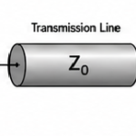
At sufficiently high frequencies, the cable must be treated as a transmission line. The distributed inductance and capacitance determine its characteristic impedance, which is important for preventing reflections at the source, cable, connector, and receiver.
Z_0\approx\sqrt{\frac{L}{C}}The actual impedance of a communication cable depends on its conductor geometry, insulation, spacing, twist, and manufacturing tolerances. This is why simply placing two wires next to each other does not reproduce the electrical behavior of a properly manufactured UTP cable.
For the broader principles of transmission-line behavior, return paths, reflections, and wired signal integrity, see Signal Integrity in Wired Systems.
Basic Construction of UTP Cable
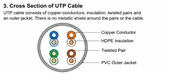
A typical UTP cable contains several basic elements: conductive cores, insulation around each conductor, twisted pairs, and an outer jacket. The exact construction varies according to the application, cable category, conductor type, fire or environmental requirements, and mechanical design.
Conductors
Conductors are commonly made from copper in communication-grade cabling. The conductor may be solid or stranded. Solid conductors are generally used where the cable remains fixed, while stranded conductors provide greater flexibility for patching and repeated movement.
Insulation
Each conductor is electrically insulated from the other conductors. The dielectric material affects capacitance, signal propagation, mechanical properties, and loss. In high-performance communication cable, the insulation geometry must remain consistent because small dimensional changes can affect impedance and signal quality.
Twisted Pairs
The insulated conductors are twisted together to form individual pairs. A multi-pair cable may contain several pairs, with each pair assigned a carefully controlled twist rate. Different twist rates help reduce predictable coupling between adjacent pairs and therefore reduce crosstalk.
Outer Jacket
The outer jacket protects the internal pairs from mechanical damage, moisture, abrasion, and the surrounding environment. The jacket itself is not the electromagnetic shield. A cable can have a substantial outer jacket and still be completely unshielded electrically.
Why UTP Is Widely Used
UTP remains attractive because it provides a useful combination of electrical performance, flexibility, cost, ease of termination, and compatibility with established communication systems. It avoids the additional conductive layers, shield-bonding requirements, and specialized termination considerations associated with many shielded cable constructions.
That does not mean UTP is always the best choice. In strong electromagnetic environments, high-density cable installations, industrial systems, or applications with demanding shielding requirements, a screened or shielded construction may provide additional protection.
The correct choice is therefore determined by the electrical environment and system requirements, not by the assumption that a shielded cable is automatically superior.
UTP in Analog and Low-Level Signal Systems
UTP is not limited to Ethernet and computer networking. Twisted balanced pairs are also valuable in analog instrumentation, sensor systems, audio, industrial control, measurement equipment, and low-level signal transmission.
This matters because a low-voltage analog signal can be extremely sensitive to a small amount of induced interference. A digital input may tolerate a certain amount of noise while still recognizing a valid logic state, whereas a sensor or precision analog front end may interpret a small unwanted voltage as a real change in the measured quantity.
Balanced twisted-pair wiring can therefore be useful even when the signal is relatively slow. Its value comes from controlling electromagnetic coupling and preserving balance, not simply from supporting a high data rate.
This broader use of twisted-pair wiring is also why UTP should be understood as an electrical transmission structure rather than simply as an “Ethernet cable.”
UTP and Shielding
UTP and shielding solve related but different problems. UTP uses pair geometry and balance to reduce susceptibility to interference, while a conductive shield provides an additional electromagnetic barrier around a cable or pair.
The distinction becomes easier to understand by comparing UTP with shielded constructions such as F/UTP, U/FTP, and S/FTP. The latter add conductive shielding at different locations within the cable structure.
For a basic introduction to shielding and the different forms used in electrical systems, see Shielding: Definition, Types and Basic Principles in Electronics.
UTP Cable Categories and Ethernet Applications
UTP describes the construction of the cable, while a cable category describes its specified transmission performance. These are related but different concepts. A cable can therefore be an unshielded twisted pair while belonging to a particular category or class intended for a defined frequency and communication performance.
This distinction is important when comparing Ethernet cables. Terms such as Cat5e, Cat6, Cat6A, Cat7, and Cat8 should not be treated as simple synonyms for UTP. The category identifies performance requirements, while the U/ F/ S notation identifies the arrangement of shielding.
UTP and Category 5e
Cat5e became widely used for structured Ethernet cabling and remains common in residential and office installations. A Cat5e cable can be constructed as U/UTP, but category and shielding should still be considered separately when identifying a cable.
The cable’s ability to support a communication link depends on more than the printed category. Conductor geometry, pair balance, impedance, insertion loss, crosstalk, connector performance, and installation practices all contribute to the final link performance.
UTP and Cat6
Cat6 introduced tighter electrical performance requirements and improved control of crosstalk compared with earlier categories. Depending on construction, Cat6 cable may be unshielded or shielded. A common unshielded construction is U/UTP Cat6.
Some Cat6 cables use a central separator to maintain greater spacing between pairs and reduce pair-to-pair coupling. The mechanical structure therefore becomes part of the signal-integrity design rather than merely serving as physical support.
UTP and Cat6A
Cat6A was developed for higher-performance Ethernet cabling and improved control of crosstalk, including coupling from neighboring cables. This becomes increasingly important as cable density and transmission bandwidth increase.
Cat6A may be manufactured with or without an overall shield. Therefore, the statement “Cat6A means shielded” is incorrect. The category and the shielding designation describe different characteristics.
Understanding U/UTP, F/UTP, U/FTP and S/FTP
A more precise way to describe balanced copper cable construction is to identify the shielding of the complete cable separately from the shielding of the individual pairs.
| Designation | Overall Shield | Individual Pair Shield |
|---|---|---|
| U/UTP | None | None |
| F/UTP | Foil | None |
| S/UTP | Braid | None |
| U/FTP | None | Foil |
| F/FTP | Foil | Foil |
| S/FTP | Braid | Foil |
The first part identifies the overall cable screen, while the second identifies whether the individual twisted pairs are screened. This notation is much more precise than using “STP” as though it described one universal physical construction.
A dedicated comparison of these constructions will examine UTP, STP, FTP, and S/FTP in greater detail, including shielding effectiveness, grounding, termination, flexibility, cost, and suitable electromagnetic environments.
UTP in Ethernet Networks
Ethernet is one of the most important applications of UTP. A conventional multi-pair Ethernet cable contains several balanced twisted pairs. Each pair is independently twisted, and the twist geometry is carefully controlled to reduce coupling between neighboring pairs.
During transmission, the active pair carries complementary electrical signals. The receiver detects the differential information while rejecting a portion of interference that appears similarly on both conductors.
The cable therefore performs two functions simultaneously: it provides a physical transmission path and it establishes an electromagnetic environment that supports balanced signaling.
Why Ethernet Uses Multiple Twisted Pairs
Using separate pairs allows multiple differential channels to coexist within one cable. However, placing several signal pairs next to one another creates the possibility of electromagnetic coupling between them.
This unwanted coupling is known as crosstalk. Cable designers control it using conductor spacing, pair geometry, dielectric design, twist-rate differences, shielding where applicable, and manufacturing tolerances.
The result is a carefully engineered balance between density, impedance, attenuation, crosstalk, flexibility, and manufacturing cost.
UTP in Telephone and Low-Frequency Communication Systems
Twisted-pair wiring predates modern Ethernet by many decades. Telephone networks used twisted conductors because balanced pairs provided substantially better rejection of interference than poorly arranged parallel wires.
The same principle remains useful in low-frequency and low-level analog systems. A signal does not need to be a gigabit data stream before electromagnetic coupling becomes a problem. A small sensor voltage, audio signal, or instrumentation circuit may be far more vulnerable to a few millivolts of induced noise than a digital input with a large logic-voltage margin.
UTP for Analog and Sensor Signals
Balanced twisted-pair wiring is particularly useful for analog signals that must travel through electrically noisy environments. Examples include sensor outputs, instrumentation signals, audio circuits, industrial measurement systems, and low-level differential signals.
Suppose the wanted differential signal is only 20 mV. If interference produces 2 mV more noise on one conductor than the other, the differential error is:
V_{error}=V_{n1}-V_{n2}If the mismatch is 2 mV, the error is already 10 percent of the intended signal. This illustrates why physical symmetry is important in low-level analog systems even when the signal frequency is relatively low.
For analog instrumentation, the cable may also be combined with a conductive shield when the electromagnetic environment is sufficiently severe. In that case, twisting controls balance while the shield provides an additional barrier against electromagnetic coupling.
UTP Versus Shielded Twisted Pair
The main difference between UTP and a shielded twisted-pair construction is the presence of a conductive electromagnetic barrier. UTP relies primarily on conductor geometry, balance, and differential operation. Shielded constructions add another mechanism for controlling electromagnetic coupling.
| Characteristic | UTP | Shielded Twisted Pair |
|---|---|---|
| Twisted conductors | Yes | Yes |
| Metallic shield | No | Yes |
| Weight | Generally lower | Generally higher |
| Flexibility | Generally simpler | Depends on shield construction |
| EMI protection | Primarily from balance and geometry | Balance plus conductive screening |
| Termination complexity | Generally lower | Can be higher |
| Grounding/bonding considerations | No cable shield to bond | Shield termination becomes important |
Neither construction is automatically better in every installation. UTP can be an excellent choice in a normal electromagnetic environment, while a shielded construction may become preferable where strong external interference, high cable density, or demanding EMC requirements justify the additional shielding.
What UTP Cannot Do
UTP should not be described as immune to electromagnetic interference. Twisting reduces coupling; it does not create a perfect electromagnetic barrier.
If the two conductors do not experience the same interference, the differential receiver cannot cancel the entire disturbance. A useful representation is:
V_{noise,diff}=V_{n1}-V_{n2}Only when the coupled interference is equal does the ideal cancellation occur. Real cables therefore depend on balance, geometry, termination quality, external field distribution, and receiver characteristics.
In severe electromagnetic environments, a conductive shield may be added to provide another layer of protection. The shield itself then becomes an engineering system requiring suitable termination and bonding.
UTP and the Broader Signal-Integrity System
UTP should never be considered in isolation from the circuitry connected to it. The source impedance, connector, PCB trace, return path, receiver, and cable all form one transmission system.
A well-designed UTP cable connected to a poorly designed PCB interface can still produce reflections, common-mode conversion, crosstalk, or excessive noise. Conversely, an excellent PCB cannot completely compensate for a badly constructed cable.
This is why cable design and PCB signal integrity are best treated as parts of one continuous electrical path rather than unrelated subjects.
UTP Does Not Mean “Cheap” or “Low Performance”
Another common misconception is that the absence of a metallic shield automatically means a UTP cable is low quality. Cable performance depends on the complete construction and the transmission requirements for which it was designed.
A carefully manufactured UTP cable can maintain controlled impedance, low insertion loss, low crosstalk, and good balance over a substantial frequency range. Its lack of a metallic shield is a deliberate design characteristic, not necessarily a manufacturing deficiency.
The more useful engineering question is therefore not “Is shielded cable better?” but rather “What electromagnetic environment and transmission requirements does this cable need to satisfy?”
UTP Cable Applications Beyond Ethernet
UTP is often associated with Ethernet, but the electrical principle behind an unshielded twisted pair is much broader. Whenever two conductors need to carry a balanced signal through an environment containing electromagnetic interference, controlled twisting can improve the symmetry of the transmission path.
UTP in Telephone Systems
Telephone networks are one of the historical foundations of twisted-pair technology. Voice signals occupy a relatively low frequency range, but long wires can still pick up interference from power systems, other telephone pairs, motors, and nearby electrical equipment. Twisting the conductors reduces the tendency of external fields to produce a large differential error in the pair.
The same balanced-pair principle remains useful in many low-frequency communication and instrumentation systems even when the signal is nowhere near the data rates associated with Ethernet.
UTP in Industrial Signals
Industrial installations often contain motors, contactors, variable-frequency drives, solenoids, switching power supplies, and long power cables. These devices can generate rapidly changing currents and electromagnetic fields that couple into nearby signal wiring.
A twisted balanced pair can reduce magnetic pickup by reducing the effective loop area and by making the two conductors experience a more similar electromagnetic environment. For particularly noisy installations, however, UTP may be supplemented or replaced by shielded cable, filtering, galvanic isolation, or other EMI-control measures.
UTP for Sensors and Instrumentation
Low-level sensor signals can benefit from twisted-pair construction even when their bandwidth is modest. The issue is not simply frequency; it is the ratio between the wanted signal and the unwanted interference.
For example, an instrumentation circuit measuring a 5 mV signal can be seriously affected by a small unequal interference voltage. If the two conductors receive 1 mV and 0.2 mV of coupled noise, the resulting differential error is:
V_{error}=1\,\mathrm{mV}-0.2\,\mathrm{mV}=0.8\,\mathrm{mV}The error is therefore 16% of the original 5 mV signal. This illustrates why balanced wiring and electromagnetic symmetry matter for precision analog circuits as much as they do for high-speed digital communication.
UTP and RS-485
RS-485 is a differential communication standard commonly implemented over twisted pair. The receiver detects the voltage difference between the two conductors, while the pair’s geometry helps reduce unwanted electromagnetic coupling.
The cable itself is only one part of the system. Termination, biasing, common-mode voltage range, grounding strategy, connector layout, cable impedance, and installation routing all influence the reliability of an RS-485 link.
This is a useful example of why the phrase “UTP cable” should not be interpreted as “Ethernet cable.” A twisted pair is a transmission medium that can support many different electrical interfaces.
UTP and Differential Interfaces
Many communication interfaces use pairs of conductors because differential signaling offers a useful way to reject common-mode interference. The basic differential quantity is:
V_{diff}=V_{+}-V_{-}If the same unwanted voltage is added to both conductors, the receiver ideally removes it when calculating the difference. In practice, finite common-mode rejection and imperfect cable balance leave some residual noise.
The physical pair must therefore remain sufficiently balanced for the electrical cancellation to work effectively. This is one of the deeper reasons why UTP cable construction is controlled much more carefully than two arbitrary insulated wires placed beside one another.
UTP Cable vs Two Ordinary Wires
It is tempting to think that a UTP cable is simply two ordinary wires twisted together by hand. Electrically, that is an oversimplification. A manufactured communication cable controls conductor diameter, insulation thickness, pair geometry, twist rate, impedance, balance, attenuation, and crosstalk.
Two wires can carry an electrical signal, but they do not automatically provide the same transmission-line characteristics as a properly manufactured UTP cable. At higher frequencies and longer distances, these differences become increasingly important.
This distinction becomes particularly relevant when users ask whether ordinary hookup wire can replace a twisted-pair communication cable. The answer depends on the signal, distance, frequency content, noise environment, and required performance; for a specification-based communication link, arbitrary wire should not be assumed to be equivalent to the specified cable.
How Twist Rate Is Selected in UTP Cable
The two conductors in a UTP pair are not twisted at an arbitrary rate. The manufacturer selects the geometry to provide the required electrical balance while controlling capacitance, inductance, attenuation, impedance, and coupling to neighboring pairs.
Increasing the number of twists per unit length can improve the averaging of external electromagnetic coupling, but it also changes the physical geometry of the pair. A tighter twist can increase the effective conductor path length and influence capacitance and other transmission characteristics.
In a multi-pair cable, the pairs can use different twist rates. If every pair had exactly the same geometric pattern, repeated alignment could increase predictable coupling between pairs. Different pair geometries help spread and reduce this coupling.
UTP Cable and Crosstalk
When several twisted pairs are placed inside the same cable, the electromagnetic field produced by one pair can couple into another. This unwanted interaction is called crosstalk.
Crosstalk has both capacitive and inductive components. Electric-field coupling is associated with mutual capacitance, while magnetic-field coupling is associated with mutual inductance. Cable designers control both mechanisms through pair geometry, separation, twist-rate selection, dielectric properties, and—where required—shielding.
At high data rates, crosstalk becomes one of the major limits on cable performance. This is why a cable category cannot be determined simply by looking at the number of wires or the amount of twisting visible from the outside.
UTP, EMI and Shielding: How the Three Concepts Relate
UTP, EMI, and shielding are related concepts, but they should not be treated as synonyms. UTP describes a cable construction. EMI describes unwanted electromagnetic interference. Shielding describes one method of controlling electromagnetic coupling.
A UTP cable can reduce the effect of interference through balanced geometry without containing a metallic shield. A shielded twisted pair adds a conductive barrier to provide additional electromagnetic control. Filtering, grounding, bonding, cable routing, and differential reception can provide additional protection.
For the broader topic of electromagnetic interference and compatibility, see EMI and EMC explained. For the basic principles of shielding, see the CircuitFeed Shielding guide.
When Should You Choose UTP?
UTP is generally attractive when the electromagnetic environment is manageable, the communication system is designed for balanced transmission, and the additional complexity of a conductive cable shield is unnecessary.
A practical choice should consider cable length, signal bandwidth, edge rate, electromagnetic environment, installation density, connector construction, grounding and bonding requirements, mechanical conditions, and the electrical specification of the interface.
A shielded cable may be justified when strong external fields are present or when emissions and immunity requirements are particularly demanding. However, choosing a shielded cable introduces additional design considerations because the shield must be correctly terminated and bonded to provide its intended benefit.
Common UTP Cable Misconceptions
UTP Means Untwisted Pair
False. UTP means Unshielded Twisted Pair. The conductors are intentionally twisted.
UTP Cannot Reject EMI
False. Twisted geometry and balanced signaling can provide substantial rejection of interference even without a metallic shield.
UTP Is Only for Ethernet
False. Twisted balanced pairs are also used in telephone systems, instrumentation, industrial communication, analog signals, and other wired interfaces.
Shielded Cable Is Always Better
Not necessarily. Shielding can improve electromagnetic protection, but the correct choice depends on the environment and the quality of shield termination, bonding, connectors, routing, and system design.
UTP and the Untwisted-Pair Confusion
The distinction between UTP and an untwisted pair deserves separate treatment because the two phrases can look deceptively similar when the abbreviation is expanded incorrectly.
An unshielded twisted pair deliberately uses twisting to maintain electromagnetic symmetry. An untwisted or irregular pair does not provide that same controlled geometry. If the two conductors have substantially different positions relative to an interference source, they can receive different induced voltages:
V_{n1}\neq V_{n2}
The residual differential noise then becomes:
V_{noise,diff}=V_{n1}-V_{n2}\neq0This is one reason arbitrary straight or unevenly routed wires should not be assumed to behave like a manufactured UTP cable. The geometry of the pair is an electrical parameter, not merely a mechanical feature.
The detailed comparison of untwisted pair, straight wires, and UTP is a separate topic because the terminology and electromagnetic behavior deserve a much deeper treatment.
UTP Cable Installation and Practical Design Considerations
The electrical performance of a UTP cable depends not only on the cable itself but also on how it is installed. A properly manufactured twisted pair can lose much of its intended performance when the pair geometry is disturbed, the cable is sharply bent, or the termination is poorly made.
This becomes particularly important at higher frequencies, where small changes in conductor spacing and geometry can alter impedance, increase reflections, or reduce the balance between the two conductors.
Do Not Untwist More Than Necessary
When terminating a UTP cable, the individual conductors must be separated enough to reach the connector contacts. Excessive untwisting, however, changes the geometry that the cable manufacturer carefully controlled.
As the untwisted section becomes longer, the conductors no longer experience the same electromagnetic environment as they did inside the cable. This can affect pair balance, crosstalk, and high-frequency transmission performance.
The practical lesson is simple: preserve the original twist as close to the termination as the connector and installation method allow.
Avoid Excessive Bending
A UTP cable is designed with a particular conductor geometry. Excessive bending, crushing, or repeated mechanical deformation can change the spacing between conductors and alter the electrical characteristics of the pair.
At low frequencies, a small geometric change may have little visible effect. At high data rates, the same deformation can contribute to impedance discontinuities, increased crosstalk, or additional signal loss.
Do Not Crush the Cable
Compression can permanently deform the insulation and change the relationship between the conductors. Since transmission-line properties depend on geometry, physical damage can become an electrical problem even when the copper conductors themselves remain continuous.
Avoid Strong Electromagnetic Sources
UTP relies on balance rather than a metallic shield, so installation routing remains important. Running sensitive twisted-pair wiring directly alongside high-current switching conductors, motor cables, or other strong interference sources can increase coupling.
Reducing the physical coupling path is often more effective than trying to compensate for a poor installation later. Separation, appropriate crossing geometry, controlled return paths, and correct cable selection all contribute to EMI performance.
UTP Connector and Termination Considerations
A cable is only one part of a communication link. The connector and termination must preserve the electrical properties of the pair as far as practical. At high frequencies, the transition from PCB trace to connector to cable can introduce discontinuities that behave as small transmission-line structures of their own.
A poor termination can create additional capacitive or inductive coupling, disturb pair balance, increase crosstalk, and introduce reflections. This is why high-performance communication systems use connectors designed specifically for the intended cable category and interface.
The same principle applies at the opposite end of the cable. A high-quality UTP cable cannot compensate indefinitely for a badly designed connector, inappropriate termination, or poorly routed PCB interface.
UTP and Characteristic Impedance
At sufficiently high frequencies, the distributed behavior of the cable becomes important. The signal no longer experiences the entire cable as one lumped resistance and capacitance. Instead, voltage and current vary along the cable as an electromagnetic wave propagates through the structure.
The characteristic impedance of an idealized transmission line can be approximated from its distributed inductance and capacitance:
Z_0\approx\sqrt{\frac{L'}{C'}}where L' and C' represent inductance and capacitance per unit length. In a real UTP cable, frequency-dependent losses and other effects mean that the actual impedance is more complicated than this simplified relationship, but the equation illustrates why conductor geometry matters.
If the impedance changes abruptly, part of a propagating signal can be reflected toward the source. The reflection coefficient at a load can be expressed as:
\Gamma=\frac{Z_L-Z_0}{Z_L+Z_0}For a perfectly matched load, Z_L=Z_0 , and the ideal reflection coefficient becomes zero. Real communication channels contain connectors, PCB transitions, cable junctions, and other discontinuities, so controlling impedance throughout the signal path is an important part of high-speed design.
UTP and Signal Attenuation
Signal amplitude decreases as it travels through a real cable. This attenuation is caused by several mechanisms, including conductor resistance, skin effect at higher frequencies, dielectric losses, and other frequency-dependent effects.
The result is that a high-frequency signal does not arrive at the receiver in exactly the same form in which it left the transmitter. Amplitude, rise time, phase, and waveform shape can all change with distance and frequency.
Cable categories and communication standards therefore place limits on insertion loss and related parameters. A UTP cable intended for a high-speed application must be manufactured with sufficiently controlled electrical characteristics to keep these losses within the required limits.
UTP and Electromagnetic Balance
One of the most important properties of a high-quality balanced cable is symmetry. The two conductors should respond similarly to external electromagnetic fields, while the differential signal should remain clearly distinguishable from common-mode disturbances.
Perfect symmetry does not exist in a practical cable. Small differences in conductor dimensions, insulation, twist geometry, connectors, PCB transitions, and installation can convert some common-mode interference into differential-mode noise.
V_{error}\propto V_{CM}\,\epsilonHere \epsilon represents a conceptual measure of imbalance. The exact relationship depends on the system, but the engineering principle is important: the better the balance, the less common-mode interference is converted into unwanted differential signal.
Why UTP Does Not Provide Perfect Common-Mode Rejection
It is sometimes said that differential transmission “cancels noise.” That statement is only true when the noise couples sufficiently equally into both conductors and the receiver has sufficient common-mode rejection.
Consider the more general case:
V_1=V_{s1}+V_{n1}
V_2=V_{s2}+V_{n2}
The receiver obtains:
V_{diff}=(V_{s1}-V_{s2})+(V_{n1}-V_{n2})
The unwanted term disappears only when V_{n1}=V_{n2}. Any difference between the two coupled noise voltages becomes part of the measured differential signal.
This is precisely why pair geometry, conductor spacing, twist consistency, connector design, and cable routing all matter. The objective is not to create a magical noise-free cable but to maintain the symmetry that allows differential reception to reject unwanted common-mode energy.
UTP in Mixed-Signal Electronic Systems
The same principles apply when a UTP cable connects a sensor, analog front end, converter, controller, or data-acquisition system. The cable should be considered part of the signal path rather than a passive piece of wire that can be ignored after the circuit schematic is completed.
For example, a sensor producing a small differential voltage may be connected through a twisted pair to an instrumentation amplifier. The twisting helps maintain electromagnetic symmetry, while the receiver’s differential architecture rejects common-mode interference. If the environment is particularly noisy, additional cable shielding, filtering, isolation, or other EMI-control techniques may be appropriate.
This is especially important in precision measurements because the acceptable noise level is determined by the signal amplitude and required accuracy, not simply by whether the system is called “digital” or “analog.”
UTP vs Ordinary Straight Wires
Two ordinary insulated wires can carry current, but they should not automatically be considered electrically equivalent to a manufactured UTP pair.
A communication-grade UTP cable has controlled conductor geometry, insulation, pair spacing, twist rate, balance, impedance, attenuation, and crosstalk performance. Randomly routed wires may have changing separation and orientation, causing the two conductors to interact differently with external electromagnetic fields.
If one conductor receives V_{n1} of interference and the other receives V_{n2} , then the residual differential noise is:
V_{n,diff}=V_{n1}-V_{n2}
When the geometry is poorly controlled, V_{n1} and V_{n2} can differ significantly. This is one of the fundamental electrical differences between a deliberately manufactured twisted pair and two loosely arranged conductors.
When UTP Is a Good Choice
UTP is particularly useful when a balanced transmission system is operating in an environment where the electromagnetic interference can be controlled without the added complexity of a conductive cable shield. Its combination of low cost, flexibility, controlled electrical performance, and simple termination makes it attractive for many communication and instrumentation applications.
A good design decision should consider the entire system: signal amplitude, frequency content, edge rate, cable length, electromagnetic environment, required noise immunity, grounding arrangement, connector design, and applicable interface specification.
Where these conditions exceed what an unshielded construction can reliably handle, the next step is not simply “use a better UTP.” Instead, the designer may move toward a shielded construction such as F/UTP, U/FTP, or S/FTP and then address the additional shield termination and bonding requirements.
Related CircuitFeed Topics
UTP is one part of a larger wired signal-integrity system. The following CircuitFeed guides provide the broader context:
- Twisted Pair Cable: Differential Signaling and EMI Reduction
- Signal Integrity in Wired Systems
- Shielding: Definition, Types and Basic Principles
- EMI and EMC Explained
The next specialized article in this cable cluster can examine the difference between UTP, STP, FTP, and S/FTP, including shielding construction, foil and braid, grounding, termination, and the environments in which each construction becomes useful.
UTP Cable Performance: What Determines the Real Electrical Quality?
The label UTP tells us that a cable is an unshielded twisted pair construction, but it does not by itself tell us how well that cable will perform in a particular application. Two UTP cables can look similar from the outside while having significantly different electrical characteristics. Conductor diameter, insulation, pair geometry, twist rate, balance, manufacturing tolerances, and category specification all influence the final transmission performance.
This is particularly important when a cable is used for a high-speed communication link or a low-level analog signal. In both cases, the electrical properties of the complete pair determine how much useful signal reaches the receiver and how much unwanted energy is introduced along the way.
Conductor Resistance and Cable Loss
Every UTP conductor has finite resistance. As current flows through the conductor, part of the electrical energy is dissipated as heat, producing voltage loss between the transmitter and receiver.
V_R=IR
For a fixed conductor material and cross-sectional area, resistance increases with length. The basic relationship is:
R=\rho\frac{l}{A}where \rho is the conductor resistivity, l is conductor length, and A is cross-sectional area.
In practical communication cable, the effective electrical path is also influenced by the twisting itself because each conductor travels a slightly longer path than the overall cable length. High-frequency losses introduce additional effects beyond ordinary DC resistance.
Skin Effect at Higher Frequencies
As frequency increases, alternating current becomes increasingly concentrated toward the outer region of a conductor. This phenomenon is known as skin effect. The effective AC resistance therefore becomes greater than the simple DC resistance.
\delta=\sqrt{\frac{2}{\omega\mu\sigma}}Here \delta is the skin depth, \omega is angular frequency, \mu is magnetic permeability, and \sigma is electrical conductivity.
Skin effect becomes one of the reasons why high-frequency cable loss increases with frequency. The cable must therefore be designed as a frequency-dependent transmission medium rather than as an ordinary DC wire.
Dielectric Loss
The insulation surrounding the conductors is not electrically perfect. The dielectric stores electric energy and also dissipates some energy as the electric field changes. This produces dielectric loss, which becomes increasingly important as frequency rises.
Consequently, both the conductor and the insulating material contribute to the attenuation of a UTP cable. Cable manufacturers must select dielectric materials and geometry that provide the required balance among propagation characteristics, mechanical strength, cost, and loss.
Propagation Delay and Pair Symmetry
A signal does not travel through a cable instantaneously. It propagates along the transmission structure at a velocity determined largely by the surrounding dielectric and the geometry of the conductors.
For differential systems, both conductors should have closely matched propagation characteristics. Any substantial asymmetry can alter the timing relationship between the two signal components and may contribute to common-mode conversion or reduced receiver performance.
This is one reason precision communication cables require tightly controlled manufacturing tolerances rather than simply relying on the visual appearance of the twist.
UTP Pair Balance and Common-Mode Conversion
An ideal balanced pair would respond identically to external interference on both conductors. Real systems are not perfectly symmetrical. The resulting imbalance can convert part of a common-mode disturbance into a differential component that the receiver cannot completely reject.
Conceptually, if the common-mode disturbance is V_{CM} and the imbalance factor is represented by \epsilon , the resulting differential error can be thought of as proportional to:
V_{DM,error}\propto \epsilon V_{CM}The expression is a conceptual relationship rather than a complete cable model, but it captures an important principle: even when a differential receiver has excellent common-mode rejection, poor physical balance can still allow environmental interference to appear in the measured signal.
UTP and Pair-to-Pair Crosstalk
A multi-pair UTP cable contains several electromagnetic structures operating close to one another. The signal on one pair can therefore couple into another pair through electric and magnetic fields.
Capacitive coupling can be represented conceptually using mutual capacitance, while inductive coupling arises from mutual inductance between current loops. Both mechanisms can produce unwanted voltages in neighboring pairs.
Twist-rate staggering, controlled pair separation, dielectric design, and cable geometry are used to keep this coupling within the limits required by the cable specification.
Near-End and Far-End Crosstalk
Crosstalk measurements are commonly discussed in terms of where the unwanted signal is observed relative to the source.
Near-End Crosstalk (NEXT) is measured at the same end of the cable as the disturbing transmitter. Far-End Crosstalk (FEXT) is measured at the opposite end. Both are important when evaluating a multi-pair transmission system.
At higher frequencies and higher cable density, interactions between separate cables can also become significant. This is often referred to as alien crosstalk.
These effects are one reason why cable categories cannot be judged simply by the number of twists visible in the cable. The entire construction must satisfy electrical performance requirements.
Why UTP Cable Has Different Twist Rates for Different Pairs
In a multi-pair UTP cable, giving every pair exactly the same twist geometry can create repeated spatial relationships between neighboring pairs. Those repeating relationships can increase predictable electromagnetic coupling.
Manufacturers therefore use different twist rates for different pairs. The result is that the conductors do not maintain the same relative geometry at every point along the cable, helping reduce persistent coupling between adjacent pairs.
This is a subtle but important point: the twisting of each pair is not designed only for external EMI rejection. It also contributes to the management of pair-to-pair crosstalk inside the cable.
UTP and Cable Length
Longer cables provide more opportunity for attenuation, crosstalk, and electromagnetic coupling to accumulate. The maximum practical distance therefore depends on the interface, cable category, frequency content, installation environment, connectors, and channel specification.
A common mistake is to assume that a cable will work reliably simply because the receiver can still detect some signal at the far end. High-speed communication requires sufficient margin, not merely detectable voltage.
The complete channel must maintain adequate signal-to-noise ratio, timing margin, insertion-loss performance, return-loss performance, and crosstalk performance for the intended interface.
UTP Cable and Shielding: When Twisting Is Not Enough
Twisting and differential signaling can provide strong immunity to many interference sources, but neither creates an impermeable electromagnetic barrier. Strong external fields, poor installation geometry, cable imbalance, high cable density, and demanding EMC requirements can justify additional shielding.
A shielded cable adds a conductive structure that can reduce electromagnetic coupling beyond what balanced twisting alone can achieve. However, the shield also introduces new engineering requirements involving connector construction, bonding, termination, and sometimes grounding.
This leads to an important design principle:
Twisting and shielding are different mechanisms, and a well-designed cable may use either one or both depending on the electromagnetic environment.
The detailed comparison of unshielded and shielded constructions belongs in the dedicated UTP, STP, FTP, and S/FTP comparison article rather than being mixed into the fundamental UTP explanation.
Can UTP Be Used for Sensitive Analog Signals?
Yes, when the cable, interface, and electromagnetic environment are appropriate. A balanced pair can be particularly useful for low-level signals because the receiver can reject common-mode interference while the cable geometry helps maintain similar coupling on the two conductors.
However, the required noise performance must be evaluated quantitatively. For a very small sensor signal, even a small residual differential interference can become significant. In such cases, the designer may use UTP together with differential amplification, filtering, isolation, careful routing, shielding, or a combination of these methods.
This is an important reminder that EMI and signal integrity are not exclusively digital-communication problems. Low-voltage analog and instrumentation systems can be exceptionally sensitive to electromagnetic interference because their useful signals may be only millivolts or microvolts.
UTP Cable Selection: What Should an Engineer Check?
Selecting UTP should begin with the electrical requirements of the application rather than with the appearance or marketing label of the cable.
- Signal type: differential, balanced analog, digital, instrumentation, or communication.
- Signal bandwidth: determine how strongly high-frequency cable behavior matters.
- Cable length: longer paths generally increase loss and susceptibility to environmental coupling.
- Electromagnetic environment: consider motors, switching equipment, power cables, radio transmitters, and other interference sources.
- Required impedance: match the cable to the intended interface and channel specification.
- Crosstalk requirements: especially important in multi-pair and high-density installations.
- Conductor construction: choose solid or stranded according to mechanical requirements.
- Termination: use connectors and installation practices appropriate for the cable performance.
- Environmental requirements: temperature, moisture, flexibility, mechanical protection, and jacket requirements.
- Certification and applicable standard: the cable must satisfy the requirements of the actual communication system.
Final Engineering Perspective on UTP
UTP is more than two insulated wires with a twist. It is a controlled electromagnetic transmission structure whose performance results from conductor geometry, dielectric properties, balance, twist rate, impedance, attenuation, crosstalk, termination, and installation.
The word unshielded describes what the cable does not contain; it does not describe an absence of electromagnetic engineering. The twisted pair itself is carefully designed to control electromagnetic coupling and support balanced transmission.
Understanding this distinction also makes the relationship among UTP, twisted pair, shielding, differential signaling, EMI, and signal integrity much clearer. UTP occupies one specific position in that larger system: it provides a controlled twisted and balanced transmission medium without an additional conductive cable shield.
Related CircuitFeed Articles
- Twisted Pair Cable: Differential Signaling and EMI Reduction
- Signal Integrity in Wired Systems
- Shielding: Definition, Types and Basic Principles
- EMI and EMC Explained
Frequently Asked Questions About UTP Cable
What does UTP stand for?
UTP stands for Unshielded Twisted Pair. It describes a cable made from twisted conductor pairs without an additional conductive shield around the cable or individual pairs.
Does UTP mean untwisted pair?
No. UTP means Unshielded Twisted Pair. The conductors are deliberately twisted. “Untwisted pair” describes a different physical arrangement and should not be used as an expansion of the UTP abbreviation.
How does UTP cable reduce electromagnetic interference?
UTP reduces interference primarily through twisted-pair geometry and balanced transmission. The conductors experience more similar electromagnetic coupling, allowing a differential receiver to reject much of the common-mode interference.
Is UTP the same as Ethernet cable?
No. UTP describes the cable construction, while Ethernet describes a family of networking technologies. Many Ethernet cables use UTP construction, but twisted-pair wiring is also used for telephone, industrial, instrumentation, and other signal applications.
Is UTP cable shielded?
No. The defining characteristic of UTP is the absence of an additional metallic cable shield. The conductors still have electrical insulation and are deliberately twisted to control electromagnetic coupling.
Can UTP cable reject EMI without a shield?
Yes. Twisting and balanced signaling can provide substantial common-mode interference rejection. However, UTP is not immune to EMI, and strong interference or poor installation can require additional shielding or other EMI-control techniques.
What is the difference between UTP and STP?
UTP is an unshielded twisted-pair construction, while STP is commonly used to describe shielded twisted-pair cable. Precise designations such as U/UTP, F/UTP, U/FTP, and S/FTP identify where the shielding is located.
Can UTP be used for analog signals?
Yes. Balanced twisted pairs can be useful for analog, instrumentation, sensor, and audio signals because twisting helps maintain electromagnetic symmetry and differential reception can reject common-mode noise.
Is UTP suitable for noisy industrial environments?
It can be, depending on the interference level, cable routing, signal characteristics, and system requirements. In severe electromagnetic environments, shielded twisted-pair cable, filtering, isolation, or improved routing may provide additional protection.
Can ordinary wires replace UTP cable?
Not necessarily. Manufactured UTP cable has controlled impedance, balance, twist geometry, attenuation, and crosstalk performance. Two ordinary wires may carry a signal but may not provide equivalent high-frequency transmission performance.
Why are different UTP pairs twisted at different rates?
Different twist rates help reduce predictable electromagnetic coupling between adjacent pairs inside a multi-pair cable and therefore help control crosstalk.
Does a higher twist rate always make UTP better?
No. Twist rate is part of an overall cable design. Changing the twist affects geometry, capacitance, conductor path length, impedance, attenuation, and crosstalk, so the rate must be optimized rather than simply maximized.
What is U/UTP?
U/UTP identifies a balanced cable with no overall metallic shield and no individual pair shields. It is the precise construction designation commonly associated with an unshielded twisted-pair cable.
Conclusion: UTP Is an Engineered Transmission Structure
UTP cable is often described simply as “unshielded twisted pair,” but that short definition hides the engineering behind its performance. The absence of a metallic shield does not mean the cable is electrically unprotected. Its primary protection against common electromagnetic interference comes from the controlled geometry and balance of the twisted pair together with the differential nature of the receiving system.
The conductors, insulation, twist rate, impedance, balance, attenuation, crosstalk, connectors, and installation all contribute to the behavior of the complete transmission path. This is why a manufactured UTP cable should not be treated as equivalent to two arbitrary wires twisted together.
UTP is also much broader than Ethernet. The same principles are useful in telephone systems, industrial communication, instrumentation, sensor wiring, audio, and other balanced signal applications. For low-level analog circuits in particular, maintaining conductor symmetry can be important because even a small residual differential noise voltage may represent a significant fraction of the wanted signal.
When the electromagnetic environment becomes more demanding, shielding can be added to the twisted-pair structure. That leads naturally to constructions such as F/UTP, U/FTP, and S/FTP, each with its own electrical and mechanical trade-offs. Understanding UTP first makes those shielded constructions much easier to understand.
Continue Through the Twisted-Pair and EMI Cluster
UTP is one part of a larger wired signal-integrity system. The following CircuitFeed articles provide the next level of detail.
- Twisted Pair Cable: Differential Signaling and EMI Reduction — the electromagnetic principles behind twisting and balanced transmission.
- Shielding: Definition, Types and Basic Principles — the fundamentals of electrical and electromagnetic shielding.
- EMI and EMC Explained — electromagnetic interference, coupling mechanisms and EMC fundamentals.
- Signal Integrity in Wired Systems — transmission lines, return paths, differential signaling, crosstalk and wired interconnect behavior.
The next dedicated cable article can examine UTP vs STP, FTP and S/FTP, concentrating on shield construction, foil and braid, grounding and bonding, EMI performance, termination, and application selection.