
What is a Twisted Pair Cable and Why Are Wires Twisted?
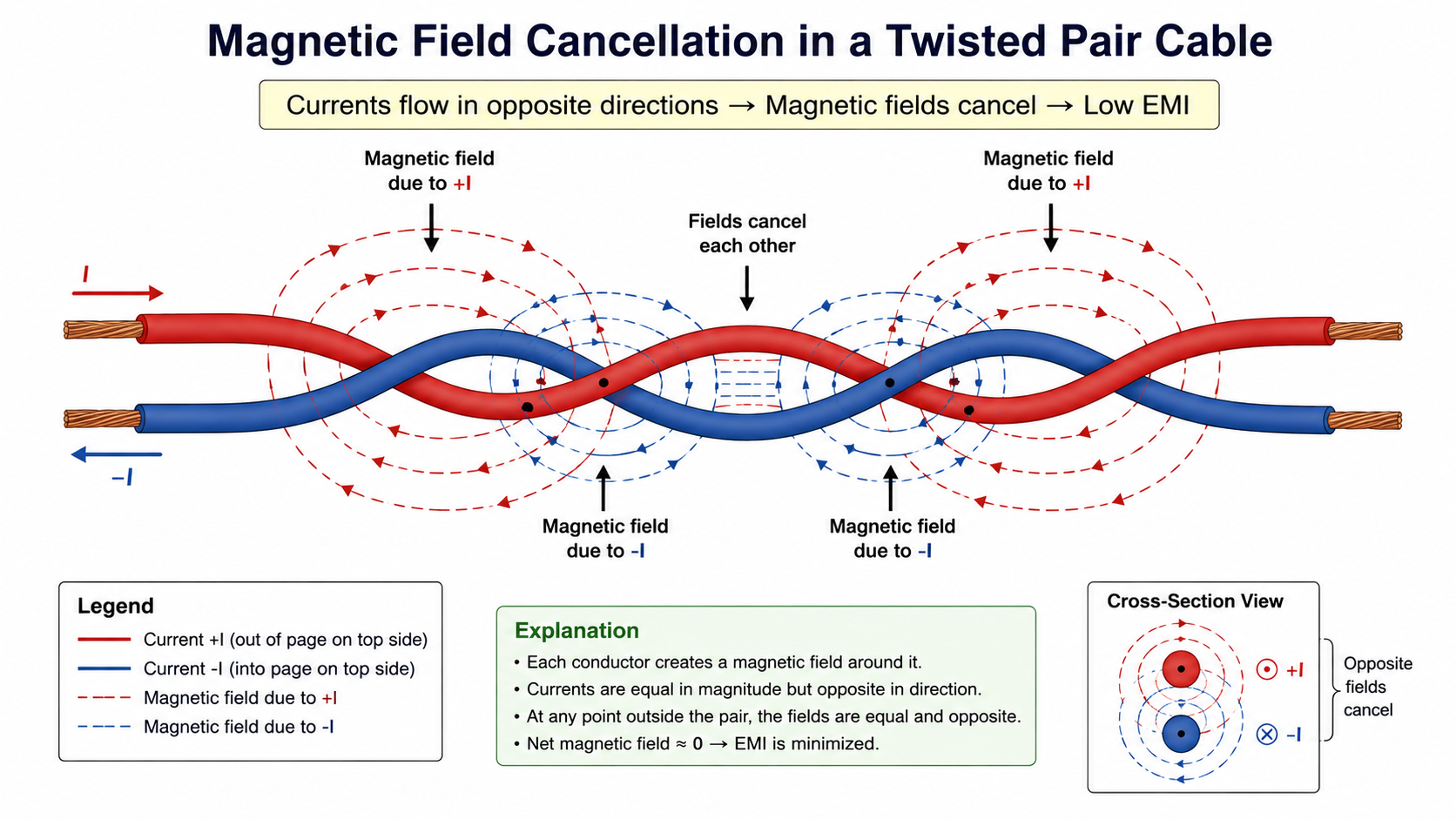
A twisted pair cable consists of two insulated conductors twisted together in a helical form. At first glance, this geometry appears simple, yet it is one of the most powerful techniques used in electrical engineering to preserve signal integrity in wired communication systems. The fundamental question that arises is straightforward: why are wires twisted instead of kept straight and parallel?
The answer lies in electromagnetic physics. When electrical signals travel through a conductor, they are accompanied by electric and magnetic fields. These fields interact with the surrounding environment and nearby conductors, leading to unwanted noise, interference, and signal degradation. A straight pair of wires behaves like an antenna, both radiating energy outward and receiving external electromagnetic interference (EMI).
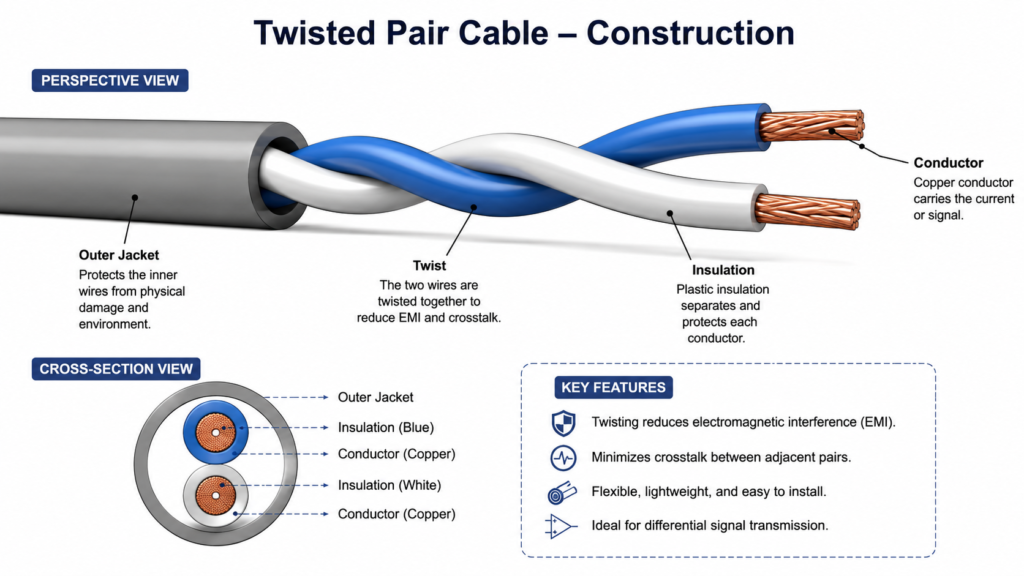
Twisting the conductors fundamentally alters this interaction. By continuously rotating the position of each conductor along the length of the cable, the electromagnetic coupling experienced by one conductor is mirrored and reversed in the other. This symmetry leads to cancellation of induced noise, significantly improving the robustness of signal transmission.
How Twisted Pair Cable Works: Field Cancellation and Noise Reduction
The operation of a twisted pair cable can be understood by examining how electromagnetic fields induce voltages in conductors.
According to electromagnetic induction, any time-varying magnetic field passing through a loop generates an induced voltage:
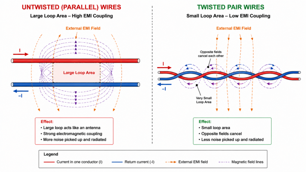
V_{induced} \propto \frac{d\Phi}{dt}Here, \phi represents the magnetic flux linking the conductor loop. In a simple untwisted wire pair, the signal and return path form a large loop area, making it highly susceptible to external electromagnetic fields. The larger this loop area, the greater the induced noise voltage.
For a straight conductor pair, the effective loop area can be approximated as:
A = d \times l
where d is the separation between conductors and l is the length of the wire. This area acts as an aperture through which magnetic fields couple into the system.
When the wires are twisted, the geometry changes dramatically. Each twist effectively reverses the orientation of the loop. As a result, the magnetic flux linking one half-twist induces a voltage of opposite polarity in the next half-twist. Over multiple twists, these induced voltages cancel each other out.
This cancellation mechanism is not perfect but is highly effective. The net induced voltage approaches zero as the twist density increases, making twisted pair cables inherently resistant to external noise sources.
Why Twisted Pair Radiates Less Electromagnetic Energy
In addition to rejecting external noise, twisted pair cables also minimize electromagnetic radiation. Any conductor carrying alternating current radiates energy, effectively acting as an antenna. The strength of this radiation depends on the current and the loop area formed by the conductor and its return path.
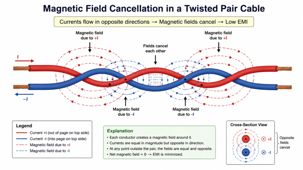
E_{radiated} \propto I \cdot ABy continuously twisting the conductors, the loop area is reduced and periodically inverted. This results in alternating radiation patterns that cancel each other in the far field. Consequently, twisted pair cables emit significantly less electromagnetic interference compared to straight or untwisted conductors.
This dual advantage—reduced susceptibility to external noise and reduced radiation—makes twisted pair cables a cornerstone of modern communication systems, from low-frequency telephone lines to high-speed digital interfaces.
Analogy with Common-Mode Chokes
The noise rejection mechanism of twisted pair cables closely resembles the operation of a common-mode choke used in power line filters. In a common-mode choke, currents flowing in opposite directions generate magnetic fields that cancel each other, suppressing noise components that are common to both conductors.
Similarly, in a twisted pair, external electromagnetic interference tends to induce the same voltage in both conductors (common-mode noise). Because the signals are typically processed in a differential manner, this common-mode component is rejected, leaving only the intended signal difference.
This principle explains why twisted pair cables are not only structurally simple but also electrically elegant, achieving noise suppression through geometry rather than additional components.
Differential Signaling: Why Twisted Pair Is Used for High-Speed Data
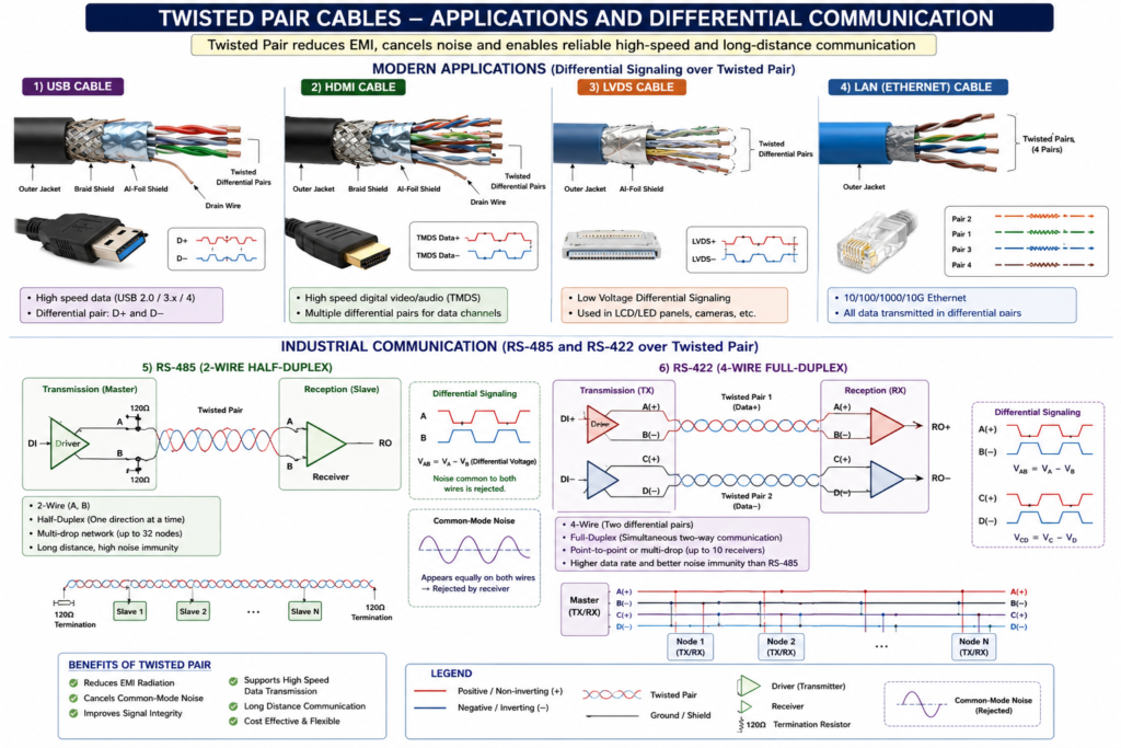
The full advantage of a twisted pair cable is realized when it is used with differential signaling. Instead of transmitting a signal with respect to ground, differential systems transmit two equal and opposite voltages along the pair of conductors. The receiver then measures the difference between these two signals rather than their absolute values.
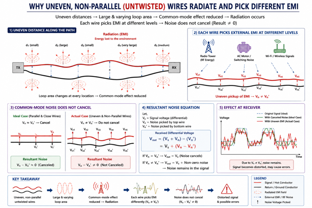
V_{diff} = V^{+} - V^{-}This configuration has a profound impact on noise immunity. External electromagnetic interference tends to couple equally into both conductors, producing what is known as common-mode noise. Because the receiver subtracts one signal from the other, any identical noise present on both lines is effectively canceled.
Twisted pair geometry ensures that both conductors experience nearly identical electromagnetic environments along their length. This symmetry is critical; without twisting, the two wires would pick up different amounts of interference, reducing the effectiveness of common-mode rejection.
As data rates increase into the megahertz and gigahertz range, maintaining this balance becomes essential. Twisted pair cables provide a controlled medium that supports high-speed differential signaling with minimal distortion and noise coupling.
Twisted Pair in Ethernet and LAN Cables (CAT5, CAT6, CAT7, CAT8)
One of the most widespread applications of twisted pair cables is in local area networks (LAN), particularly Ethernet communication. Standard Ethernet cables contain multiple twisted pairs, each carefully designed with different twist rates to minimize crosstalk between adjacent pairs.
Category-rated cables define the performance of twisted pair systems:
CAT5 and CAT5e cables are commonly used for 100 Mbps to 1 Gbps networks, while CAT6 and CAT6a extend performance to higher frequencies and support multi-gigabit data rates. CAT7 and CAT8 cables further improve shielding and bandwidth, enabling high-speed data transmission in data centers and enterprise environments.
Each pair in these cables carries differential signals, ensuring reliable communication even in electrically noisy environments. The use of twisted pair technology in Ethernet demonstrates its scalability from low-frequency analog signals to high-speed digital communication.
Twisted Pair in USB Interfaces (USB 2.0, USB 3.x, USB4)
Universal Serial Bus (USB) communication relies heavily on twisted pair conductors. In USB 2.0, a single differential pair labeled D+ and D− carries data between devices. The twisting ensures that high-speed signals remain synchronized and resistant to external noise.
As USB technology evolved to USB 3.x and USB4, the number of differential pairs increased significantly. These newer standards incorporate multiple high-speed lanes, each consisting of twisted differential pairs capable of operating at gigabit and multi-gigabit data rates.
At such high frequencies, even small imbalances in conductor geometry can lead to reflections and signal distortion. Twisted pair construction ensures consistent impedance and balanced signal propagation, which are essential for maintaining signal integrity in high-speed USB communication.
Industrial Communication: RS-485 and RS-422
In industrial environments, where electrical noise from motors, switching devices, and power systems is significant, twisted pair cables are indispensable. Communication standards such as RS-485 and RS-422 use differential signaling over twisted pair to achieve robust and long-distance data transmission.
RS-485 systems, in particular, can operate over distances exceeding hundreds of meters while maintaining reliable communication. The combination of twisted pair geometry and differential signaling allows these systems to reject common-mode noise and operate in harsh electromagnetic environments.
Twisted Pair in High-Speed Video and Display Interfaces
Modern high-speed interfaces such as HDMI and LVDS (Low Voltage Differential Signaling) also rely on twisted pair conductors. In HDMI cables, multiple differential pairs carry high-frequency digital video data using Transition Minimized Differential Signaling (TMDS).
LVDS systems use low voltage swings and differential signaling over twisted pairs to achieve high data rates with low power consumption. These systems are widely used in display panels, embedded systems, and high-speed data links.
The consistent theme across all these applications is the reliance on twisted pair geometry to maintain signal integrity, reduce electromagnetic interference, and support high-speed data transmission.
Why Twisted Pair Remains Essential in Modern Electronics
From Ethernet networks and USB interfaces to industrial communication and high-speed video transmission, twisted pair cables remain a foundational technology. Their ability to suppress noise, reduce radiation, and support differential signaling makes them uniquely suited for modern electronic systems.
Even as wireless technologies continue to evolve, wired communication based on twisted pair cables persists due to its reliability, low latency, and resistance to interference. The simplicity of twisting two conductors continues to solve complex electromagnetic challenges in both low-frequency and high-speed applications.
Construction of Twisted Pair Cable: Solid vs Stranded Conductors
The electrical and mechanical performance of a twisted pair cable depends not only on its geometry but also on the type of conductors used. Two primary conductor constructions are employed: solid conductors and stranded conductors. Each has distinct advantages depending on the application.
Solid conductors consist of a single continuous copper core. They exhibit lower electrical resistance and reduced signal attenuation, making them ideal for fixed installations such as structured cabling in buildings and long-distance communication lines. Because of their rigidity, solid conductors maintain consistent geometry, which helps preserve controlled impedance and minimizes signal distortion.
In contrast, stranded conductors are composed of multiple thin copper strands twisted together to form a single conductor. This construction increases flexibility and mechanical durability, allowing the cable to withstand repeated bending and movement. As a result, stranded twisted pair cables are commonly used in patch cords, portable devices, and applications where mechanical stress is expected.
From a signal integrity perspective, solid conductors are generally preferred for high-frequency and high-speed data transmission, while stranded conductors are selected for their mechanical advantages in dynamic environments.
Twist Rate and Its Impact on Noise and Crosstalk
The effectiveness of a twisted pair cable is strongly influenced by its twist rate, defined as the number of twists per unit length. Increasing the twist rate improves the cable’s ability to reject electromagnetic interference by ensuring more frequent reversal of the conductor positions.
Each twist introduces a phase inversion in the induced noise voltage. As the number of twists increases, the cumulative noise tends to cancel more effectively, reducing the net interference observed at the receiver.
However, a higher twist rate also increases the capacitance between conductors due to closer proximity over shorter intervals. This introduces a trade-off between noise immunity and signal attenuation. At higher frequencies, increased capacitance can lead to greater signal loss and reduced bandwidth.
To optimize performance, practical twisted pair cables use carefully selected twist rates that balance noise rejection and signal integrity. In multi-pair cables, each pair is often twisted at a slightly different rate to minimize crosstalk between adjacent pairs, a technique known as twist rate staggering.
Characteristic Impedance and Controlled Transmission
At high frequencies, twisted pair cables behave as transmission lines rather than simple conductors. Their electrical behavior is governed by distributed inductance and capacitance, resulting in a characteristic impedance that must be matched to the source and load to prevent signal reflections.
Z_0 = \sqrt{\frac{L}{C}}Here, L and C represent the inductance and capacitance per unit length of the cable. Maintaining a consistent impedance is essential for high-speed digital communication, where impedance mismatches can cause reflections, signal distortion, and data errors.
Twisted pair cables used in communication systems are typically designed with characteristic impedances of 100 ohms for differential signaling. This standardization ensures compatibility across devices and communication protocols.
Categories of Twisted Pair Cables (CAT Standards)
Twisted pair cables are classified into categories based on their electrical performance, bandwidth, and shielding characteristics. These categories define the maximum data rates and operating frequencies supported by the cable.
CAT3 cables were historically used for telephone systems and early data communication. With the rise of Ethernet, CAT5 and CAT5e became widely adopted, supporting data rates up to 1 Gbps. CAT6 and CAT6a improved performance by reducing crosstalk and increasing bandwidth, enabling multi-gigabit communication.
Higher categories such as CAT7 and CAT8 introduce enhanced shielding and tighter manufacturing tolerances, allowing operation at significantly higher frequencies. These cables are commonly used in data centers and high-performance networking environments where signal integrity is critical.
The evolution of CAT standards reflects the increasing demand for higher data rates and improved noise immunity, with twisted pair technology adapting to meet these requirements through refined construction and materials.
How Construction Influences Real-World Performance
The performance of a twisted pair cable is the result of multiple interacting factors, including conductor type, twist rate, insulation material, and shielding. A well-designed cable maintains geometric consistency along its length, ensuring stable impedance and predictable signal behavior.
In practical systems, these design parameters determine how effectively the cable can transmit high-speed signals, reject interference, and minimize losses. As data rates continue to increase, the importance of precise cable construction becomes even more significant, bridging the gap between theoretical design and real-world performance.
History of Twisted Pair Cable in Communication Systems
The concept of twisting conductors to reduce interference dates back to the early days of telecommunication. In the late 19th century, telephone engineers discovered that parallel wires used for voice transmission were highly susceptible to electromagnetic interference from nearby power lines and other communication circuits.
A practical solution emerged when engineers began twisting the wire pairs along their length. This simple modification dramatically reduced noise pickup and crosstalk, allowing clearer voice transmission over longer distances. The technique quickly became standard in telephone networks and laid the foundation for modern communication cabling.
Over time, twisted pair technology evolved from basic voice communication lines to high-performance data transmission systems. With the development of digital communication, Ethernet networks, and high-speed interfaces, twisted pair cables have been continuously refined to support increasing bandwidth and stricter signal integrity requirements.
Limitations of Twisted Pair Cables
Despite their widespread use and effectiveness, twisted pair cables are not without limitations. While twisting significantly reduces electromagnetic interference, it does not provide complete shielding. In environments with extremely high levels of electromagnetic noise, additional shielding techniques such as foil or braided shields may be required.
At very high frequencies, signal attenuation becomes more pronounced due to skin effect and dielectric losses. These factors limit the maximum distance and data rate that can be achieved with twisted pair cables. As a result, alternative transmission media such as coaxial cables or optical fibers are used for ultra-high-speed or long-distance communication.
Another limitation arises from impedance discontinuities caused by connectors, improper termination, or cable damage. These discontinuities lead to signal reflections, which degrade signal quality and can result in data errors in high-speed systems.
Nevertheless, for a wide range of applications, twisted pair cables offer an optimal balance between performance, cost, flexibility, and ease of installation.
Twisted Pair vs Untwisted Wires: Why Geometry Matters
To fully appreciate the effectiveness of twisted pair cables, it is useful to compare them with untwisted or straight wire configurations. In untwisted wires, the loop area between the signal and return path remains constant and relatively large, making the system highly susceptible to electromagnetic interference.
In contrast, twisting continuously alters the spatial relationship between the conductors, effectively averaging out the induced noise along the length of the cable. This geometric approach to noise reduction eliminates the need for complex filtering in many applications.
This comparison highlights a key principle in electrical engineering: physical layout and geometry can be as important as circuit design in determining system performance.
Conclusion: Why Twisted Pair Remains a Fundamental Technology
Twisted pair cables represent a remarkable example of how a simple geometric modification can solve complex electromagnetic problems. By reducing loop area, canceling induced noise, and supporting differential signaling, twisted pair cables enable reliable communication across a wide range of applications.
From early telephone systems to modern Ethernet networks, USB interfaces, and high-speed digital communication, twisted pair technology continues to play a central role in electronics. Its ability to adapt to increasing data rates while maintaining signal integrity ensures its continued relevance in both current and future communication systems.
Related Topics and Further Reading
To deepen your understanding of signal transmission and cable design, explore the following related topics:
- Unshielded Twisted Pair (UTP) Cable and Applications
- Shielded Twisted Pair (STP, FTP, SFTP) and EMI Protection
- Untwisted Pair vs Twisted Pair: Noise and Signal Integrity Comparison
- Differential Signaling in High-Speed Communication
- Electromagnetic Interference (EMI) and Crosstalk in Cables
These interconnected topics form a comprehensive knowledge base for understanding modern wired communication systems and will further strengthen the conceptual framework established in this article.



Leave a Reply