
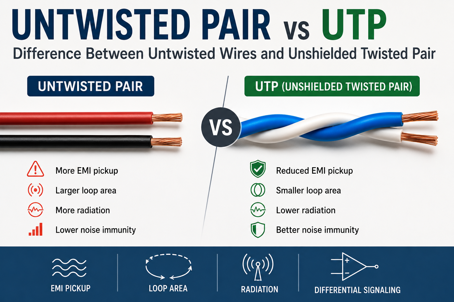
The terms “untwisted pair” and UTP can look confusingly similar, but they do not describe the same thing. UTP stands for Unshielded Twisted Pair. The conductors in a UTP cable are deliberately twisted together; what is missing is an additional metallic shield around the pair or cable. An untwisted pair, in contrast, describes two conductors that are not deliberately twisted together.
This distinction is important because twisting is not merely a mechanical way of keeping two wires together. It changes the electromagnetic behavior of the complete signal path. The geometry of the conductors affects loop area, electromagnetic coupling, common-mode rejection, crosstalk, radiation, and the amount of external interference that can be converted into unwanted differential voltage.
For that reason, UTP should never be expanded as “untwisted pair.” UTP means Unshielded Twisted Pair, while an untwisted arrangement is a different physical geometry with different signal-integrity characteristics.
This article examines the difference from an electrical-engineering perspective, including what happens when two conductors remain straight or follow uneven paths, why twisting improves electromagnetic symmetry, and why the difference can matter even in low-voltage analog and low-current circuits.
Does UTP Mean Untwisted Pair?
No. UTP means Unshielded Twisted Pair. The abbreviation describes two characteristics of the cable:
U = Unshielded
T = Twisted
P = Pair
Therefore:
UTP = Unshielded Twisted Pair
The word unshielded refers to the absence of a separate conductive shield. It does not mean that the conductors are unprotected, and it does not describe the pair as being untwisted.
A typical UTP cable can contain several twisted pairs inside one outer jacket. Each pair consists of two insulated conductors that are intentionally twisted along the length of the cable. Ethernet cables are a familiar example, but twisted balanced pairs are also used in telephone systems, industrial communication, instrumentation, sensors, audio, and other signal applications.
What Is an Untwisted Pair?
Untwisted pair is best understood as a descriptive term for two conductors that form a pair but are not deliberately twisted together. The wires may be straight and parallel, separated by a relatively constant distance, or routed in a loose and irregular manner.
Unlike UTP, “untwisted pair” should not automatically be interpreted as the name of a standardized modern cable category. Its electrical behavior depends strongly on how the conductors are physically arranged, how far apart they are, the signal being transmitted, and the electromagnetic environment around them.
Two untwisted wires can still carry an electrical signal perfectly well. A short connection carrying a low-frequency or relatively large signal may work without difficulty. The problem appears when electromagnetic coupling, signal integrity, distance, or noise sensitivity becomes important.
Why Does Twisting Change the Electrical Behavior?
The fundamental difference between twisted and untwisted conductors is their interaction with electromagnetic fields. Any changing current and voltage produces electromagnetic fields, while external changing fields can induce unwanted voltages in nearby conductors.
For a changing magnetic field, Faraday’s law gives the induced electromotive force:
V_{ind}=-\frac{d\Phi}{dt}
where \Phi is the magnetic flux linking the relevant conductor loop.
The physical area enclosed by the signal and return conductors therefore matters. For a simple pair of parallel wires, the loop area can be approximated as:
A\approx d\,l
where d is the separation between the conductors and l is the length of the path.
A larger loop area generally provides more opportunity for a changing magnetic field to couple into the signal path. This is one reason why keeping the forward and return conductors close together is a fundamental technique for reducing electromagnetic pickup.
What Happens to an Untwisted Pair?
Imagine two straight conductors carrying a differential signal. If the conductors remain separated by a fixed distance, the geometry of the loop remains substantially the same along the complete route. An external electromagnetic field therefore sees a similar loop orientation over a long section of the cable.
Now consider a less controlled arrangement in which the distance between the wires changes from one location to another. The loop area is no longer constant. At some points the conductors may be close together; at others they may be much farther apart. Their orientation relative to an interference source can also change.
This creates an important problem for differential signaling: the two conductors may no longer receive the same induced interference.
Common-Mode Noise Only Cancels When the Two Wires See Nearly the Same Noise
A differential receiver responds to the difference between its two input voltages. Let the wanted signal be represented by the two conductor voltages and let the unwanted noise coupled into the conductors be V_{n1} and V_{n2}. The residual differential noise is:
V_{noise,diff}=V_{n1}-V_{n2}
If the external interference couples equally into both conductors, then:
V_{n1}=V_{n2}
and consequently:
V_{noise,diff}=0
This is the ideal common-mode cancellation condition. The receiver sees the same unwanted voltage on both conductors and subtracts it away.
But if the conductors have different physical relationships with the interference source, the induced voltages can become unequal:
V_{n1}\neq V_{n2}
The differential receiver then sees a non-zero noise component:
V_{noise,diff}\neq0
This is the critical electrical reason why conductor geometry matters. A differential receiver cannot cancel the portion of interference that has already become differential.
How Twisting Improves the Situation
Twisting continuously exchanges the physical positions of the two conductors. Over one section, the first conductor occupies one side of the pair; farther along the cable, it occupies the position previously occupied by the second conductor.
This repeated exchange causes the two conductors to experience a more similar average electromagnetic environment over the length of the cable. An external field that couples more strongly into one conductor during one portion of the twist can couple more strongly into the other conductor in another portion.
The objective is therefore not to make every tiny section of the cable perfectly immune to electromagnetic interference. Instead, the geometry makes the overall coupling more balanced.
Ideally, the complete pair approaches the condition:
V_{n1}\approx V_{n2}
so that:
V_{noise,diff}=V_{n1}-V_{n2}\approx0
This is one of the central reasons twisted-pair construction is so useful for balanced communication and instrumentation.
For the deeper treatment of twisted-pair electromagnetic behavior, see Twisted Pair Cable: Differential Signaling and EMI Reduction.
Untwisted Pair Is Not Necessarily a Bad Connection
It is important not to turn the previous explanation into an absolute rule that every untwisted connection is electrically unacceptable. Electronics contains countless short connections made with ordinary straight conductors, and many work perfectly well.
The issue is one of electrical requirements. If the signal is short, slow, relatively large, and surrounded by little electromagnetic interference, the disadvantages of an untwisted arrangement may be negligible.
As the signal becomes smaller, faster, longer, or more sensitive to noise, the geometry of the conductors becomes increasingly important. A connection that appears perfectly acceptable at low frequency can produce measurable interference or signal-integrity problems when the same physical arrangement is used for a more demanding circuit.
Why Uneven Untwisted Wires Pick Up More Interference
The electrical problem with an untwisted pair becomes much clearer when the two conductors do not remain at the same distance from an interference source. In real installations, wires are rarely perfectly straight and parallel for their entire length. One wire may pass closer to a motor cable, switching regulator, transformer, PCB trace, or other source of electromagnetic energy while the other takes a slightly different path.
The resulting imbalance means that the two conductors no longer behave as equally exposed pickup elements. One conductor may receive a larger induced voltage than the other, so the unwanted signal is no longer purely common-mode.
Unequal Distance Produces Unequal Coupling
Consider an external interference source located closer to one conductor than the other. The electric field and magnetic field generated by that source do not necessarily have the same magnitude and direction at both conductors. Consequently, the induced voltages can differ:
V_{n1}\neq V_{n2}
The differential receiver therefore sees:
V_{noise,diff}=V_{n1}-V_{n2}
The important point is that the original interference source does not have to be directly connected to either conductor. Electromagnetic coupling alone can generate the unwanted differential voltage.
Changing Wire Separation Makes the Coupling Change Along the Route
Now consider two wires whose spacing changes continuously along the route. The effective loop area is no longer constant. At one point the conductors may be close together, while farther along they may separate substantially.
Because electromagnetic coupling depends on geometry, the interference induced in the pair also changes with position. Instead of a controlled and approximately symmetrical transmission structure, the pair becomes a sequence of different coupling conditions.
This is one reason why merely keeping two wires “generally close” is not equivalent to constructing a proper twisted pair. The objective is not only small average separation; it is controlled and balanced geometry along the entire transmission path.
Untwisted Wires Can Also Radiate More Electromagnetic Energy
The same geometry that makes a pair more vulnerable to receiving interference can also affect how much electromagnetic energy it radiates. A time-varying current produces a magnetic field, and changing voltages produce electric fields around the conductors.
When the forward and return currents are physically close and arranged symmetrically, their associated electromagnetic fields tend to cancel strongly in the far field. Increasing the loop area or separating the conductors reduces that cancellation and can increase unwanted radiation.
This is an important reason why an untwisted or poorly routed pair can behave more like an unintended antenna than a carefully arranged twisted pair.
The Signal Path Forms an Electromagnetic Loop
Whenever current leaves a source and eventually returns to it, a current loop exists. In a two-wire signal connection, one conductor carries the forward current while the other provides the return path. The electromagnetic field surrounding this loop depends strongly on the physical relationship between the two conductors.
A simplified engineering picture is:
Source → forward conductor → load
  ↑                         ↓
  └────── return conductor ─┘
If the forward and return conductors are close together, much of their electromagnetic field interaction is confined to a small region around the pair. If they are widely separated, the loop becomes larger and the external field produced by the loop becomes more significant.
Why Twisting Helps Radiation Cancellation
Twisting repeatedly exchanges the physical positions of the two conductors. This causes the orientation of the local current loop to alternate along the cable. At distances sufficiently large compared with the cable dimensions, the radiation contributions from successive sections can partially cancel.
The cancellation is frequency- and geometry-dependent rather than perfect at every point in space. Nevertheless, maintaining a tightly controlled pair geometry can substantially reduce the unwanted external field compared with a poorly arranged loop of wires.
This is one reason twisted-pair wiring is useful not only for reducing susceptibility to interference but also for reducing the amount of electromagnetic energy that the wiring can couple into its surroundings.
Receiving and Radiating Are the Same Problem Seen From Opposite Directions
An important way to understand EMI is that a conductor arrangement capable of efficiently coupling energy outward can often also couple energy inward. The same geometry that allows a cable to radiate can allow it to act as a receiving structure.
Therefore, an irregular untwisted signal route can suffer from two related problems:
- It can radiate unwanted electromagnetic energy into nearby circuits.
- It can receive electromagnetic energy from nearby sources.
Twisted-pair geometry reduces both effects by maintaining a much more controlled relationship between the forward and return conductors.
Why Common-Mode Cancellation Gets Worse When the Wires Are Far Apart
The phrase “common-mode noise” sometimes creates the impression that any interference reaching two wires will automatically cancel in a differential receiver. That is not true. The interference must be sufficiently similar on both conductors.
Suppose an external source produces approximately:
V_{n1}=20\,\mathrm{mV}on one conductor and:
V_{n2}=17\,\mathrm{mV}on the other. The receiver does not see 20 mV of common-mode noise that can all disappear. It sees a differential noise component of:
V_{noise,diff}=20\,\mathrm{mV}-17\,\mathrm{mV}=3\,\mathrm{mV}That 3 mV is now part of the differential signal and cannot be removed by ideal common-mode subtraction.
The example is intentionally simple, but it captures the central reason why physical symmetry matters. A small mismatch between the two conductors can produce a substantial error when the desired signal itself is small.
This Matters Even More for Low-Voltage Analog Signals
The importance of controlled pair geometry is not limited to Ethernet or other digital communication systems. A low-level analog circuit may carry only a few millivolts, making even a small residual interference voltage significant.
Imagine an instrumentation circuit measuring:
V_{signal}=5\,\mathrm{mV}If an irregular untwisted route causes only 0.5 mV of residual differential interference, the relative error is:
\frac{0.5\,\mathrm{mV}}{5\,\mathrm{mV}}\times100=10\%A 10% unwanted component can be unacceptable in a precision measurement even though 0.5 mV appears electrically small in an ordinary circuit.
This is why twisted-pair wiring is valuable for sensors, instrumentation, audio, balanced analog signals, and other low-level circuits in addition to high-speed communication.
Untwisted, Parallel and Unevenly Routed Wires Are Not the Same Case
It is useful to distinguish several physical arrangements rather than treating every non-twisted connection as one identical structure.
| Arrangement | Typical Geometry | Electromagnetic Behavior |
|---|---|---|
| Twisted pair | Conductors exchange positions repeatedly | Good geometric averaging and balance |
| Parallel pair | Conductors remain close and parallel | Can work well over short distances; coupling depends on spacing and environment |
| Untwisted, widely separated | Large loop area | Greater susceptibility and radiation potential |
| Unevenly routed pair | Changing separation and orientation | Unequal coupling and greater common-mode-to-differential conversion |
Therefore, the phrase “untwisted pair” should not be interpreted as meaning that every such connection has exactly the same electrical behavior. Geometry, frequency, length, source and load impedance, and electromagnetic environment determine the actual result.
Why Two Wires Can Work for One Circuit but Fail in Another
A short pair of ordinary wires can be entirely satisfactory for a low-frequency control signal and fail when used for a sensitive communication link. The reason is not that the copper suddenly becomes incapable of carrying current. The electrical requirements of the signal path have changed.
As frequency content, distance, signal sensitivity, or electromagnetic interference increases, the previously negligible effects of loop area, parasitic inductance, capacitance, radiation, pickup, impedance, and crosstalk become more important.
This is the same general principle behind signal-integrity engineering: an interconnect that behaves like an ideal wire in one application can become an active electromagnetic component in another.
For the broader treatment of this transition in wired circuits, see Signal Integrity in Wired Systems.
Can Untwisted Wires Still Transmit a Signal?
Yes. An untwisted pair can transmit electrical signals. Twisting is not a fundamental requirement for electrical current to travel from a source to a load. The reason engineers twist conductors is that the geometry of the transmission path can strongly influence noise pickup, radiation, crosstalk, impedance, and signal integrity.
A short connection carrying a relatively large, low-frequency signal may work perfectly well with ordinary straight conductors. Problems become more likely when the connection becomes longer, the signal becomes smaller or faster, or the surrounding electromagnetic environment becomes more aggressive.
When Is an Untwisted Pair Acceptable?
There is no universal frequency at which an untwisted pair suddenly stops working. Acceptability depends on the complete electrical system. Important variables include conductor spacing, cable length, source and load impedance, signal amplitude, rise time, surrounding interference, and the amount of noise the receiver can tolerate.
For example, two short wires carrying a slow control signal inside a quiet enclosure may perform adequately without twisting. The same wires routed several meters beside a motor cable may behave very differently because the electromagnetic coupling path has become much more significant.
Likewise, a low-level analog signal may require much better control of conductor geometry than a large digital control voltage. The important quantity is not simply the absolute noise voltage but the noise relative to the wanted signal.
Untwisted Pair in Low-Voltage and Low-Current Analog Circuits
Analog circuits are an important example because they are sometimes overlooked when discussing twisted-pair wiring. A precision sensor, instrumentation amplifier, thermocouple interface, ADC input, microphone circuit, or other low-level analog source may produce only millivolts or less.
Suppose the wanted signal is:
V_{signal}=2\,\mathrm{mV}An unwanted differential component of only:
V_{noise}=0.2\,\mathrm{mV}represents:
\frac{0.2}{2}\times100=10\%of the desired signal. A wiring arrangement that appears harmless in a power or digital circuit can therefore be unacceptable in a precision analog measurement.
This is one reason twisted balanced wiring is frequently used in instrumentation. The objective is to keep the two conductors electromagnetically similar so that interference tends to appear as common-mode voltage rather than differential error.
Why Straight Parallel Wires Can Still Be Better Than Randomly Routed Wires
It is important to distinguish a controlled straight pair from a randomly routed pair. Two conductors that remain close and approximately parallel can have considerably better electromagnetic symmetry than two wires that repeatedly separate, cross, and change orientation.
For the straight parallel case, the physical relationship between the conductors is relatively predictable. In an irregular route, one conductor may approach an interference source while the other moves away from it, creating different pickup voltages along different sections of the path.
Therefore, “not twisted” does not automatically mean “worst possible.” The important engineering parameter is the quality and consistency of the transmission geometry.
Untwisted Pair and Common-Mode Rejection
Common-mode rejection depends on the interference being sufficiently similar at both inputs of the receiver. Let the interference appearing on the two conductors be:
V_{n1}=V_n+\Delta V_1V_{n2}=V_n+\Delta V_2The receiver sees the difference:
V_{noise,diff}=(V_n+\Delta V_1)-(V_n+\Delta V_2)V_{noise,diff}=\Delta V_1-\Delta V_2The ideal common component \(V_n\) disappears, but the unequal components remain. The more asymmetrical the pair becomes, the greater the potential for common-mode interference to be converted into differential noise.
Untwisted Wires, Radiation and Loop Area
The same current loop that receives magnetic interference can also radiate electromagnetic energy. A signal and its return current form a loop, and the electromagnetic field generated by that loop depends on its physical dimensions and the frequency of the current.
When the outgoing and return conductors are close together, their fields tend to cancel more effectively in the surrounding space. When the conductors are separated, the loop becomes larger and the cancellation becomes less complete.
For an untwisted pair with varying separation, the loop geometry can also change from one location to another. Some sections may therefore radiate more strongly than others. This is one reason poor wiring geometry can create unexpectedly strong electromagnetic emissions even when the current itself is relatively small.
A Cable Can Be Both an EMI Receiver and an EMI Transmitter
The receive and transmit problems are closely related. A conductor arrangement capable of coupling electromagnetic energy efficiently from a current loop into surrounding space can also couple external electromagnetic energy back into the same loop.
In practical terms, an untwisted or widely separated pair can act as an unintended antenna structure. An external radio-frequency source may induce unwanted voltage into it, while a rapidly changing signal on the pair can radiate energy toward another circuit.
This is why EMI control is fundamentally a geometry problem as well as a component-selection problem. Changing the physical arrangement of the conductors can sometimes produce a larger improvement than adding another filter after the signal has already been contaminated.
Twisting Is Not the Same as Shielding
An untwisted pair, a UTP pair, and a shielded twisted pair solve the electromagnetic problem at different levels. Twisting controls the geometry and balance of the signal pair. A metallic shield adds a conductive barrier around the conductors. Differential reception provides another level of rejection by responding primarily to the voltage difference between the conductors.
These mechanisms are complementary rather than interchangeable.
Twisting
   ↓
Improves pair symmetry

Differential signaling
   ↓
Rejects common-mode voltage

Shielding
   ↓
Reduces electromagnetic coupling
A properly engineered communication system may use all three mechanisms together. For the broader shielding concept, see Shielding: Definition, Types and Basic Principles.
Why Untwisted Pair Is More Sensitive to Installation Geometry
A manufactured twisted pair has a controlled geometry throughout its length. An untwisted installation depends much more heavily on the person routing the wires. Small changes in separation or direction can change the coupling between the pair and nearby interference sources.
For example, imagine two conductors running next to a switching power cable. If both remain at approximately the same distance from the interference source, the induced voltages may remain relatively similar. If one conductor moves significantly closer while the other remains farther away, the balance is disturbed.
This produces precisely the condition that a differential system wants to avoid:
V_{n1}\neq V_{n2}Twisting provides a passive way of repeatedly exchanging those positions, which is why it is so effective compared with simply attempting to keep two arbitrary wires “roughly together.”
Can You Replace UTP With Untwisted Wires?
Sometimes, but the answer depends entirely on the application. For a short, low-speed connection in a low-noise environment, ordinary wires may be sufficient. For a specified high-speed communication interface, long balanced signal path, or sensitive analog measurement, replacing the specified twisted pair with arbitrary untwisted wires can change the electrical characteristics enough to cause unreliable operation.
Before substituting wires, the engineer should consider at least the required impedance, signal bandwidth, cable length, attenuation, crosstalk, noise immunity, and electromagnetic environment.
The correct question is therefore not simply “Can two straight wires carry the signal?” They can. The better question is “Will their electromagnetic and transmission-line characteristics remain within the requirements of this particular system?”
Untwisted Pair and the Broader Signal-Integrity Problem
The difference between twisted and untwisted conductors illustrates a broader principle of wired signal integrity: the physical interconnect is part of the circuit. Its geometry determines resistance, inductance, capacitance, electromagnetic coupling, characteristic impedance, radiation, and susceptibility.
For this reason, a signal cannot be fully analyzed by looking only at the transmitter and receiver schematic. The cable or wires between them also form an electrical structure that may become increasingly important as the signal frequency content, distance, or sensitivity increases.
For a wider introduction to these principles, see Signal Integrity in Wired Systems.
Untwisted Pair, Straight Wires and Differential Signaling
The phrase untwisted pair can describe several practical wire arrangements, but the electromagnetic behavior depends on the actual geometry. Two conductors may remain straight and close together, remain straight but widely separated, or follow irregular paths with changing spacing. These arrangements should not be assumed to have identical signal-integrity performance.
For a differential system, the important quantity is the voltage difference between the two conductors:
V_{diff}=V_1-V_2The differential receiver can reject interference only to the extent that the unwanted voltage appears similarly on both conductors. Physical symmetry therefore becomes an important part of the electrical design.
A Closely Spaced Straight Pair Is Better Than a Widely Separated Pair
If two conductors remain close together and approximately parallel, the loop area between them is smaller than it would be if they were separated by a large distance. This generally reduces magnetic coupling and also keeps the forward and return currents electromagnetically closer to one another.
However, a straight parallel pair still does not provide the same spatial averaging as a twisted pair. The same conductor remains on the same side of the pair for the complete length of the route, so any asymmetry relative to an external interference source can persist along the entire path.
Why Randomly Routed Wires Are Particularly Problematic
Consider two wires that begin together but gradually separate, bend around different obstacles, and later come together again. Although they still form a signal pair electrically, their electromagnetic geometry has become highly irregular.
At one location the first conductor might be closer to a switching node, while at another location the second conductor might be closer. The coupled noise therefore varies independently along the two paths.
In simplified form:
V_{n1}(x)\neq V_{n2}(x)where the variable \(x\) represents position along the cable. The problem is therefore not limited to the total noise voltage at the receiver; the imbalance can change continuously along the entire transmission path.
Changing Loop Area Along a Wire Route
For an idealized straight pair, the separation may be approximately constant. In an irregular pair, the separation can be represented as a function of position:
d=d(x)
The local loop area therefore also changes along the route. A simple conceptual representation is:
A(x)\approx d(x)\,dx
The real electromagnetic problem is more complicated because the field has a direction and the loop is distributed in three dimensions, but the important engineering idea remains: changing conductor separation produces changing electromagnetic coupling.
Why Twisting Creates Better Average Symmetry
A twisted pair deliberately alternates the position of the two conductors. If an external field couples more strongly into one conductor during one section of the twist, the geometry later reverses and the other conductor occupies the corresponding position.
Over many twists, the pair therefore approximates a more balanced average electromagnetic exposure. This is one reason why twisted-pair cable can maintain good common-mode rejection without requiring a metallic shield.
The effect is closely related to the basic principle already seen in differential signaling:
V_{noise,diff}=V_{n1}-V_{n2}The engineering goal is to make the two coupled noise voltages as similar as practical:
V_{n1}\approx V_{n2}Untwisted Pair and Radiation From the Signal Loop
The same forward-and-return current path that determines magnetic susceptibility also influences radiation. When the current loop becomes physically larger, the associated electromagnetic field can extend farther into the surrounding space.
At frequencies where the interconnect dimensions are electrically significant, an irregular wire route can therefore become an unintended radiating structure. The effect becomes more important as the signal contains faster transitions and higher-frequency spectral components.
Keeping the forward and return conductors close together reduces the area over which their fields are separated. Twisting adds another level of spatial averaging and can reduce the net far-field radiation from successive sections of the pair.
Radiation and Reception Are Reciprocal Problems
An interconnect that is capable of radiating electromagnetic energy can also act as a receiving structure. This is why an untwisted or poorly controlled pair can suffer from both emissions and susceptibility.
A nearby RF source, switching node, motor drive, or digital circuit can inject energy into the wiring. The same wiring, when carrying a rapidly changing signal, can emit energy into another nearby circuit.
The two problems should therefore be considered together:
Poor geometry
      ↓
Larger or irregular loop
      ↓
More electromagnetic coupling
      ↓
       ┌───────────────┐
       ↓               ↓
   More pickup     More radiation
       ↓               ↓
   EMI at victim   EMI to others
Why This Matters for USB, Ethernet and Other Balanced Interfaces
High-speed interfaces use controlled differential structures because the electrical margin available at the receiver can be small compared with the possible interference environment. A transmission path must preserve pair balance, impedance, timing, and controlled coupling from the transmitter to the receiver.
Replacing a specified twisted-pair structure with arbitrary straight wires can therefore change more than noise pickup. It can also alter characteristic impedance, propagation behavior, crosstalk, and reflections.
This is particularly important as signal transition times become short. Even when the nominal data rate is not extremely high, fast edges contain significant high-frequency content that makes the physical interconnect increasingly important.
Why the “Untwisted Pair” Concept Also Matters in Analog Circuits
The same physics applies to low-frequency analog systems. A sensor output, instrumentation signal, microphone connection, thermocouple interface, or low-level ADC input may have a very small wanted voltage. Even a modest imbalance in electromagnetic pickup can become significant relative to the signal.
For example, if:
V_{signal}=10\,\mathrm{mV}and the wiring produces:
V_{noise,diff}=1\,\mathrm{mV}then the interference represents:
\frac{1}{10}\times100=10\%of the wanted signal. The signal does not have to be a high-speed Ethernet waveform for wiring geometry to become important.
What Happens When the Pair Is Close to a Power Cable?
Power cables carrying rapidly changing current can produce both electric and magnetic fields. If a signal pair runs close to the power cable, some of this energy can couple into the signal conductors.
If both signal conductors follow nearly identical paths and remain close together, much of the coupled interference can remain common-mode. If one conductor is routed farther away, crosses a different path, or loops around an obstacle, the coupling can become unequal.
This is why practical cable routing is an important part of EMI control. The geometry of the installation can determine whether an interference source produces mostly common-mode noise or a significant differential error.
The Difference Between an Untwisted Pair and UTP Is Therefore Electrical, Not Just Terminological
The most useful conclusion is that UTP is not simply “two wires without shielding.” Its twisted geometry is part of the electrical design. The conductor arrangement controls how the pair responds to external electromagnetic fields and how its own signal currents interact with the surrounding environment.
An untwisted pair can still work, but its performance depends much more strongly on the exact route and environment. Once the wires become unevenly spaced, widely separated, or differently exposed to interference, common-mode cancellation becomes less effective and both susceptibility and radiation can increase.
This distinction is the reason an ordinary pair of straight wires should not automatically be considered an electrical equivalent of UTP.
Where This Leads in Practical Cable Design
Once the basic difference between twisted and untwisted geometry is understood, the next questions are naturally about UTP, STP, FTP, and S/FTP, cable shielding, pair balance, crosstalk, and termination. These are separate design choices built on the same electromagnetic principles.
For the basic UTP construction and applications, see UTP Cable: Unshielded Twisted Pair Explained.
For EMI fundamentals, see EMI and EMC Explained. For shielding fundamentals, see Shielding: Definition, Types and Basic Principles.
Untwisted Pair vs Twisted Pair: A Practical Electrical Comparison
The difference between an untwisted pair and a twisted pair becomes clearer when the two arrangements are compared as complete electrical transmission paths. Both can carry voltage and current, but they do not present the same electromagnetic environment to the signal.
| Characteristic | Untwisted Pair | Twisted Pair |
|---|---|---|
| Conductor arrangement | Conductors remain substantially untwisted | Conductors are deliberately twisted |
| Geometric symmetry | Depends strongly on installation | More consistently controlled |
| Loop geometry | Can be large or irregular | More tightly controlled |
| Common-mode noise rejection | Highly dependent on wire placement | Generally improved by balanced geometry |
| External EMI pickup | Can be higher when geometry is poor | Reduced through twisting and balance |
| Radiation potential | Can increase with larger loop area | Generally reduced by close, balanced geometry |
| Crosstalk control | Depends strongly on physical routing | Controlled through pair geometry and twist |
| High-speed transmission | Not inherently controlled | Manufactured cables can provide controlled characteristics |
| Installation sensitivity | High when wires are irregularly routed | Lower because the pair geometry is built into the cable |
This comparison does not mean that every twisted pair is automatically superior to every untwisted connection. The correct interpretation is that twisting provides a controlled electromagnetic geometry that makes the transmission path more predictable.
What Happens When the Two Wires Are Kept Close Together?
Keeping two untwisted wires close together is already an effective improvement compared with separating the outgoing and return conductors by a large distance. The reduced separation decreases the physical loop area and therefore generally reduces magnetic coupling.
However, the two conductors still remain in fixed positions. If an external source is asymmetric relative to the pair, one conductor can experience greater electric-field or magnetic-field coupling than the other.
A twisted pair repeatedly exchanges those positions. This means that an external field does not continuously favor the same conductor along the entire length of the cable.
What Happens When Wire Spacing Becomes Uneven?
Uneven spacing is particularly important because it can produce common-mode to differential-mode conversion. If both conductors experience almost identical interference, a differential receiver can reject much of it. If the conductors experience different interference, the difference remains in the received signal.
Suppose the unwanted voltages change with position along an irregular route:
V_{n1}=V_{n1}(x)V_{n2}=V_{n2}(x)The residual differential disturbance becomes:
V_{n,diff}(x)=V_{n1}(x)-V_{n2}(x)There is therefore no single constant “noise voltage” describing the entire route. The electromagnetic behavior can change from one section to another.
Untwisted Pair in Audio and Low-Level Analog Wiring
Balanced audio and instrumentation systems provide a useful example of why this subject is broader than Ethernet. A low-level analog signal may have relatively modest bandwidth but still require excellent rejection of external interference.
For a microphone, sensor, or instrumentation connection, the desired signal may be much smaller than the interference generated by nearby power systems. A balanced pair helps because the receiver can respond primarily to the difference between the two conductors.
If the external interference couples equally to both conductors, it behaves approximately as common-mode voltage. If the physical geometry causes unequal coupling, some of that disturbance becomes differential error.
This is why even a low-frequency analog circuit can benefit from a carefully arranged twisted pair.
Untwisted Pair in DC and Low-Speed Circuits
There are many situations where an untwisted pair is entirely practical. Short DC connections, simple control signals, LED wiring, relay connections, and other relatively insensitive circuits may not require the electromagnetic symmetry of a communication-grade twisted pair.
In these applications, the dominant design concerns may instead be voltage drop, conductor heating, mechanical strength, insulation, connector reliability, or cost.
The mistake is not using untwisted wires. The mistake is assuming that an arrangement suitable for a low-sensitivity circuit will automatically behave the same way when transferred to a sensitive or high-speed signal path.
Untwisted Pair and Transmission-Line Behavior
As the signal edge rate and physical length increase, the interconnect can no longer be treated as an ideal lumped wire. The distributed electrical properties of the conductors begin to matter.
A transmission line contains distributed resistance, inductance, capacitance, and conductance. The simplified characteristic impedance relationship is:
Z_0\approx\sqrt{\frac{L'}{C'}}For an arbitrary pair of wires, these distributed parameters may vary significantly along the path. Changing conductor separation changes capacitance and inductance, while changes in the surrounding dielectric and wire orientation can alter the electrical environment further.
A manufactured twisted-pair cable is designed to keep these parameters sufficiently controlled for its intended performance class. Random untwisted wiring does not automatically provide that control.
Why an Irregular Pair Can Produce Reflections
If the effective characteristic impedance changes along the transmission path, part of a propagating signal can be reflected. The reflection coefficient for a simple load transition is:
\Gamma=\frac{Z_L-Z_0}{Z_L+Z_0}This is another reason why the phrase “just use two wires” can be misleading for high-speed communication. The issue is not only electromagnetic noise pickup; the physical structure can also alter the propagation and reflection characteristics of the signal.
Can Untwisted Wires Be Used for Differential Signaling?
Yes. Differential signaling does not mathematically require the conductors to be twisted. A differential receiver can measure the difference between two conductors regardless of whether the pair is twisted.
The advantage of twisting is that it helps maintain the electromagnetic symmetry required for good common-mode rejection. An untwisted arrangement can still work when the conductors are short, closely coupled, and exposed to a controlled environment.
The distinction is therefore:
Differential signaling
        =
electrical signaling method

Twisted pair
        =
physical transmission geometry
The two are complementary but not identical concepts.
Untwisted Pair vs UTP: The Most Important Terminology Rule
The safest way to remember the difference is:
UTP is twisted but unshielded.
An untwisted pair is not deliberately twisted.
The two terms therefore describe different physical arrangements. Calling UTP “untwisted pair” changes the meaning of the abbreviation and can lead to the wrong assumption about how the cable controls electromagnetic interference.
The Relationship Between Untwisted Pair, UTP and Shielded Cable
The three concepts can be viewed as progressively different levels of control over the transmission environment:
Untwisted / uncontrolled pair
        ↓
physical geometry depends on routing

Twisted pair
        ↓
controlled conductor relationship

UTP
        ↓
twisted pair without metallic shield

Shielded twisted pair
        ↓
twisted pair + conductive electromagnetic barrier
This does not mean that every application needs the most controlled or most heavily shielded construction. Engineering design is a matter of matching the transmission structure to the required signal quality and electromagnetic environment.
The Broader Lesson: Wires Are Part of the Circuit
The comparison between untwisted and twisted conductors illustrates a fundamental signal-integrity principle: the physical interconnect is part of the electrical circuit.
Its resistance, inductance, capacitance, loop area, mutual coupling, characteristic impedance, and physical relationship with surrounding conductors all influence the signal. At sufficiently high frequencies or sufficiently low signal levels, the wiring can no longer be treated as an invisible connection between two circuit blocks.
This is why careful wire routing, pair geometry, shielding, grounding, and differential transmission all belong to the same broader field of wired signal integrity.
Where This Fits in the CircuitFeed Knowledge Cluster
This article addresses the terminology and electromagnetic difference between untwisted and twisted conductors. The deeper cable and signal-integrity topics are covered separately so that each subject can be examined in detail.
- UTP Cable — construction, operation, performance, and applications of Unshielded Twisted Pair.
- Twisted Pair Cable — electromagnetic principles behind twisting, differential signaling, and EMI reduction.
- Signal Integrity in Wired Systems — transmission lines, impedance, return current, crosstalk, and wired interconnect behavior.
- EMI and EMC Explained — electromagnetic interference, coupling mechanisms, emissions, and immunity.
- Shielding — basic electrical and electromagnetic shielding concepts.
Practical Examples of Untwisted and Twisted Wire Arrangements
The difference between untwisted and twisted wiring becomes easier to understand when the conductors are considered in actual installations. The same pair of copper wires can behave very differently depending on whether the wires remain together, separate around an obstacle, run beside a noisy power cable, or form a large loop between the source and load.
Example 1: Two Short Wires in a Low-Noise Circuit
Suppose a small electronic module sends a slow control signal to another module located only a few centimeters away. The two conductors are short, remain close to one another, and are surrounded by little electromagnetic activity.
In this situation, ordinary untwisted wires may work perfectly well. The loop area is small, the coupling distance is short, and the signal may have sufficient amplitude to tolerate a small amount of induced noise.
There is no engineering requirement that every electrical connection must be twisted. Twisting becomes valuable when it solves a specific electromagnetic or signal-integrity problem.
Example 2: Two Wires Routed Several Meters Beside a Motor Cable
Now consider a much longer connection routed next to a motor cable or switching power line. The nearby power circuit can generate changing magnetic and electric fields. If the two signal conductors are separated or take different paths, the electromagnetic coupling into each conductor can become substantially different.
If the induced voltages are:
V_{n1}=8\,\mathrm{mV}and:
V_{n2}=3\,\mathrm{mV}then the differential interference becomes:
V_{noise,diff}=8\,\mathrm{mV}-3\,\mathrm{mV}=5\,\mathrm{mV}A twisted pair can improve the situation by repeatedly exchanging the conductor positions and maintaining a much more symmetric electromagnetic relationship along the route.
Example 3: Sensor Cable Near a Switching Power Supply
Consider a sensor producing only a few millivolts connected to an analog front end. A nearby switching regulator contains rapidly changing currents and voltages, which can generate both electric-field and magnetic-field interference.
If the two sensor conductors are loosely routed, one may pass close to the switching node while the other follows a different path. The interference therefore becomes unequal and appears partly as differential noise.
Using a twisted pair keeps the two conductors together and improves their electromagnetic symmetry. If the environment remains too noisy, the system may additionally require shielding, filtering, physical separation, or isolation.
Straight Parallel Pair vs Twisted Pair
A straight parallel pair is not automatically a bad transmission line. In fact, many controlled transmission structures use conductors that remain parallel. What matters is whether their geometry is controlled and whether the two conductors remain electrically balanced.
A properly routed parallel pair has predictable spacing and orientation. An arbitrary pair of wires may not. The problem with random wiring is therefore not simply the absence of twisting; it is the absence of a controlled transmission geometry.
For low-frequency signals over short distances, a straight pair may be entirely adequate. For longer or more sensitive connections, twisting provides a convenient and repeatable way to maintain the desired relationship between the conductors.
Why “Close Together” Is Not the Same as “Twisted”
Keeping two wires close together is useful because it reduces the physical loop area. However, the same conductor remains on the same side of the pair along the route. If an external source is asymmetric, one conductor can therefore remain more strongly coupled to the source over the complete distance.
Twisting changes this relationship continuously. The conductor that was closer to the interference source later occupies the position of the other conductor. The pair therefore averages the external coupling over many successive sections.
This geometric averaging is one of the fundamental advantages of twisting.
Untwisted Wires and Crosstalk
Untwisted conductors can also create greater crosstalk when multiple signal paths run close together. Electric fields create capacitive coupling, while changing currents create magnetic coupling.
If one signal wire is physically closer to a neighboring circuit than its return conductor, the coupling into the pair can become unbalanced. This can make the victim circuit more susceptible to interference and can also increase the amount of unwanted energy radiated into nearby conductors.
Twisted-pair construction reduces these effects by controlling the geometry of the signal and return conductors. In multi-pair cables, different twist rates are also used to reduce predictable pair-to-pair coupling.
Why Twisted Pair Is Especially Useful for Balanced Signals
The benefit of twisting is strongest when the receiving system itself is balanced. A differential receiver calculates a voltage difference, so the cable geometry should make the two conductors experience nearly identical external interference.
Conceptually, the received differential voltage can be written as:
V_{diff}=(V_{s1}+V_{n1})-(V_{s2}+V_{n2})which becomes:
V_{diff}=(V_{s1}-V_{s2})+(V_{n1}-V_{n2})The wanted differential signal is retained, while only the equal portion of the unwanted noise cancels. Any imbalance appears in the second term.
Untwisted Pair and Common-Mode Chokes Are Not the Same Solution
A common-mode choke and a twisted pair both exploit electromagnetic symmetry, but they operate in different ways. A twisted pair establishes a balanced physical transmission geometry, while a common-mode choke is a magnetic component designed to impede common-mode current.
The two techniques can also be used together. A communication cable may use twisted conductors to maintain balance and a common-mode choke at the interface to suppress common-mode currents that remain after transmission through the cable.
This illustrates a broader EMI-design principle: several independent control mechanisms can reinforce one another when each is applied to the appropriate part of the signal path.
When Shielding Becomes Useful
If twisting alone does not provide enough immunity, a conductive shield can be added around the pair or cable. The shield provides another electromagnetic-control mechanism that is fundamentally different from the geometry of the twisted conductors.
For example, an industrial sensor cable may use twisted conductors for balance and a foil or braided shield for additional protection from strong external fields. The shielding system then requires an appropriate termination and bonding strategy.
This is why the concepts should be kept separate:
Twisted pair
    ↓
controls pair geometry

Differential receiver
    ↓
rejects common-mode voltage

Shield
    ↓
reduces electromagnetic coupling

Filter
    ↓
attenuates unwanted frequency components
These techniques address different portions of the overall EMI problem.
Practical Routing Rules for an Untwisted Pair
When a twisted pair is unavailable or an untwisted connection must be used, several simple practices can reduce the resulting electromagnetic problems.
- Keep the forward and return conductors close together.
- Avoid unnecessarily large loops.
- Keep both conductors on the same route as much as practical.
- Avoid routing one conductor close to a noise source while the other remains farther away.
- Increase physical separation from high-current switching or motor conductors.
- Cross strong power-field sources at an appropriate angle rather than running parallel for long distances.
- Use differential reception when the interface supports it.
- Consider shielding or filtering when the electromagnetic environment requires additional protection.
These measures do not transform an arbitrary wire pair into a manufactured UTP cable, but they can significantly improve the electromagnetic behavior of a simple connection.
A Useful Engineering Rule
The practical rule is simple: keep the signal conductor and its return path physically close and electrically symmetrical. Twisting is one of the most effective passive ways to achieve this over an extended flexible cable.
If the two conductors follow substantially different paths, the electrical symmetry is weakened. Once that happens, common-mode rejection becomes less effective because the two conductors no longer receive the same interference.
This principle applies equally to communication wiring, low-level analog signals, instrumentation, sensor circuits, industrial control, and many other wired systems.
Summary of the Untwisted-Pair Problem
An untwisted pair is not inherently unusable. Its suitability depends on the signal and environment. The difficulty is that its electromagnetic behavior depends strongly on the exact wire arrangement, whereas a manufactured twisted pair provides a much more controlled geometry.
When the conductors are unevenly spaced or routed differently, the two wires can receive different amounts of electromagnetic interference. In that case:
V_{n1}\neq V_{n2}and therefore:
V_{noise,diff}\neq0The same lack of controlled geometry can increase the radiation and reception of electromagnetic energy. Twisting reduces these problems by repeatedly exchanging conductor positions and improving the average symmetry of the pair.
That is the central reason why an untwisted pair should not be confused with UTP: UTP is an engineered twisted transmission structure, while an untwisted pair describes a different physical arrangement whose performance depends much more strongly on how the wires are routed.
Related CircuitFeed Topics
The concepts in this article connect directly to the broader CircuitFeed signal-integrity and EMI knowledge structure:
- UTP Cable — how Unshielded Twisted Pair is constructed and why it behaves differently from arbitrary wires.
- Twisted Pair Cable and Differential Signaling — deeper treatment of twisting, electromagnetic coupling, and noise reduction.
- EMI and EMC Explained — the broader source, coupling-path, and victim model for electromagnetic interference.
- Shielding — how shielding complements twisted-pair geometry.
- Signal Integrity in Wired Systems — transmission-line and interconnect principles behind the behavior of practical wires and cables.
Why Untwisted Wires Can Become an Unintentional Antenna
An untwisted pair does not automatically behave like an antenna, but its geometry can make it much more susceptible to electromagnetic coupling than a closely controlled twisted pair. The important factors are the physical length, conductor separation, current direction, signal frequency content, and the relationship between the wire path and surrounding electromagnetic sources.
A signal conductor always has a return-current path. The two together form an electromagnetic structure. When that structure becomes physically large compared with the electrical wavelength or contains large current loops, the surrounding electromagnetic field can become increasingly important.
A Larger Loop Produces Stronger Magnetic Coupling
Consider a signal current flowing through one wire and returning through another. If the wires are widely separated, the enclosed loop area increases. A changing external magnetic field can then couple more strongly into that loop.
Conceptually, the linked magnetic flux can be expressed as:
\Phi=\int_A \mathbf{B}\cdot d\mathbf{A}where \mathbf{B} is the magnetic flux density and A is the loop surface. Increasing the effective loop area can increase the flux linked by the circuit and therefore increase the induced voltage when the field changes.
The Same Loop Can Radiate Energy
The reciprocity of electromagnetic systems means that the same physical structure that can receive energy from an external field can also couple energy outward. A larger and poorly controlled current loop can therefore become a more effective source of radiated interference.
This is particularly relevant when the signal contains fast transitions. A digital waveform is not composed only of its repetition frequency; its fast edges contain higher-frequency spectral components that can interact strongly with the physical interconnect.
Therefore, a low-frequency control signal with very slow transitions may tolerate an untwisted connection, while a rapidly switching signal using the same wires may create measurable electromagnetic emissions.
Uneven Wire Spacing Can Produce Both Pickup and Radiation
An especially important case is a pair whose separation changes at different points along the route. The wires may start close together, separate around a connector, run near different circuit elements, and then approach each other again.
At each section, the loop geometry is different. The conductor-to-conductor coupling changes, the relationship to nearby fields changes, and the balance of the pair changes.
In simplified form, the residual noise can be thought of as a distributed quantity:
V_{noise,diff}=\int \left(k_1(x)-k_2(x)\right)\,dxwhere the expression is conceptual rather than a complete electromagnetic field solution. It represents the idea that different coupling along the two conductors can accumulate into a net differential disturbance at the receiver.
Why a Twisted Pair Reduces This Geometric Imbalance
In a twisted pair, each conductor repeatedly changes sides. The geometry therefore alternates rather than remaining fixed. A conductor that is close to an external field source during one part of the twist becomes farther away during another part.
The resulting averaging effect improves the balance of the pair over its length. This is one reason why twisting can reduce both electromagnetic pickup and unwanted radiation without requiring a continuous metal shield.
It is important to say “reduce” rather than “eliminate.” Real cables still have finite imbalance, imperfect twist geometry, connector discontinuities, bending, nearby structures, and frequency-dependent losses.
Why UTP Works Without a Metal Shield
This brings us back to the meaning of UTP. The cable is unshielded, but it is still twisted. The pair therefore receives an important degree of electromagnetic protection from its geometry and balance.
A metallic shield and a twisted pair attack the interference problem through different mechanisms. Twisting primarily improves the symmetry of the signal and return conductors. A conductive shield changes the electromagnetic boundary around the cable and can reduce coupling from external fields or contain fields generated by the cable.
This is why UTP can perform very well in a suitable environment without being equivalent to shielded cable.
When Untwisted Wires Become a Practical EMI Problem
An untwisted arrangement deserves closer attention when one or more of the following conditions apply: the cable is long, the wanted signal is small, the signal edges are fast, the environment contains strong switching currents, the pair runs near RF sources, or the receiver has a small noise margin.
The problem becomes particularly serious when several of these conditions occur simultaneously. A low-level sensor cable routed several meters beside a motor drive, for example, has very different requirements from a few-centimeter control connection on a quiet PCB.
In such cases, the engineer may need to control not only the pair geometry but also routing, shielding, filtering, grounding, bonding, connector construction, and the return-current path.
The Importance of Return Current
The phrase “signal wire” can create the impression that only one conductor matters. Electromagnetically, the return path is equally important. The fields generated by the forward and return currents depend on their relative positions.
When the return conductor is kept close to the signal conductor, the external field produced by the current loop is generally reduced compared with a large separated loop. This principle applies whether the connection is a PCB trace over a reference plane, a twisted pair cable, or a simple two-wire connection.
Therefore, an untwisted pair with a distant return path can be considerably worse than two untwisted conductors that remain close together.
Untwisted Pair on a PCB
The same idea appears on printed circuit boards. Two signal traces may be intended to act as a pair, but if one trace takes a different path, changes spacing, crosses gaps in the reference plane, or loses a well-controlled return path, the pair’s electromagnetic symmetry can degrade.
The physical problem is therefore not limited to cables. The broader principle is that signal and return paths should remain electromagnetically well controlled.
This is one of the reasons signal-integrity engineering treats the interconnect as part of the circuit rather than as an ideal connection between circuit blocks.
A Useful Way to Visualize the Difference
UNTWISTED / IRREGULAR

Source ────────────────┐
                       │
                  changing spacing
                       │
Load  ─────────────────┘

    Different electromagnetic exposure
                  ↓
            Vn1 ≠ Vn2
                  ↓
      residual differential noise


TWISTED PAIR

Source ════════════════╗
       alternating      ║
       conductor        ║
       positions        ║
Load   ════════════════╝

      More balanced exposure
                  ↓
            Vn1 ≈ Vn2
                  ↓
       better noise rejection
The diagrams are simplified, but they capture the key idea: twisting does not make electromagnetic interference disappear; it makes the two conductors interact with the surrounding electromagnetic environment in a more balanced manner.
Why This Matters More as Signal Frequency Increases
As the frequency content of a signal increases, the physical dimensions of the interconnect become increasingly important. A conductor may no longer behave as an ideal lumped wire, and its distributed inductance and capacitance begin to influence signal propagation.
Very fast digital transitions can therefore make an apparently short wire electrically significant. This is why the same pair of ordinary wires can work for a slow control signal yet produce ringing, reflections, crosstalk, or EMI when reused for a fast interface.
The broader relationship is:
Faster signal edges
       ↓
More high-frequency content
       ↓
Greater sensitivity to geometry
       ↓
Transmission-line effects
       ↓
Greater importance of routing,
pair balance, return path and EMI control
There Is No Universal “Untwisted Pair Frequency Limit”
It would be misleading to state that untwisted wires are acceptable below one particular frequency and unacceptable above it. There is no universal cutoff because the result depends on cable length, conductor spacing, signal amplitude, edge rate, source impedance, load impedance, electromagnetic environment, and the permitted error or noise level.
A useful engineering comparison is not simply frequency versus wire type, but electrical size and noise margin versus the required performance.
Untwisted Pair Is a Useful Description, Not a Modern Cable Standard
For SEO and technical clarity, it is important to keep the terminology precise. An article about “untwisted pair” should explain what the phrase means without presenting it as a modern standardized cable category equivalent to UTP, STP, or other structured-cabling designations.
The useful concept is the physical arrangement: two conductors form a pair but remain substantially untwisted. The electrical consequences then depend on how those conductors are routed and what signal they carry.
This makes the term especially useful when discussing the difference between ordinary wiring and controlled twisted-pair transmission.
The Central Answer
UTP and untwisted pair are not the same. UTP is Unshielded Twisted Pair: the conductors are intentionally twisted and the additional metal shield is absent. An untwisted pair has no such intentional twisting, so its electromagnetic performance depends much more strongly on conductor spacing, routing, loop area, and the surrounding environment.
When the two conductors experience unequal interference, the unwanted voltage does not cancel completely:
V_{noise,diff}=V_{n1}-V_{n2}\neq0When their exposure is more symmetrical:
V_{n1}\approx V_{n2}and the differential interference is reduced.
That is the fundamental electrical reason why twisted-pair geometry matters, even though two ordinary untwisted wires can still carry a signal successfully in many simple applications.
Frequently Asked Questions About Untwisted Pair
What is an untwisted pair?
An untwisted pair is a descriptive term for two conductors used together as a signal path but not deliberately twisted around one another. Their electromagnetic performance depends strongly on spacing, routing, length, signal characteristics, and the surrounding environment.
Does UTP stand for untwisted pair?
No. UTP stands for Unshielded Twisted Pair. The conductors are intentionally twisted. The “unshielded” part means that an additional metallic shield is not present.
What is the difference between UTP and untwisted pair?
UTP is a twisted-pair cable construction without an additional metallic shield. An untwisted pair has conductors that are not deliberately twisted. Because the geometry is different, their electromagnetic coupling and signal-integrity behavior can also be different.
Can untwisted wires carry a signal?
Yes. Untwisted wires can carry electrical signals, especially over short distances and in relatively quiet environments. Problems become more important when the signal is small, fast, long-distance, or exposed to significant electromagnetic interference.
Why are wires twisted in a twisted pair?
Twisting improves the electromagnetic symmetry of the pair. It causes the conductors to exchange physical positions along the cable, which helps average external electromagnetic coupling and improves common-mode noise rejection.
Does twisting completely eliminate EMI?
No. Twisting reduces electromagnetic coupling but does not make a pair immune to interference. Imperfect balance, connectors, routing, strong external fields, and other system effects can still produce residual noise.
Why does an untwisted pair receive more interference?
An untwisted or irregular pair can expose its two conductors differently to nearby electric and magnetic fields. This can produce unequal induced voltages, so the interference is no longer purely common-mode and cannot be completely canceled by a differential receiver.
Can untwisted wires radiate electromagnetic interference?
Yes. A signal and its return path form a current loop, and a larger or poorly controlled loop can increase electromagnetic radiation. Fast signal transitions can make this effect more significant because they contain higher-frequency components.
Are untwisted wires always unsuitable for high-speed signals?
Not as an absolute rule, but arbitrary untwisted wires do not automatically provide the controlled impedance, balance, crosstalk performance, or electromagnetic behavior required by a specified high-speed interface. The complete signal path must meet the requirements of the application.
Can a straight parallel pair work better than randomly routed wires?
Yes. A closely spaced, consistently routed parallel pair can have more predictable electromagnetic behavior than two wires whose separation and orientation change significantly. Twisting provides an additional way to maintain balanced exposure along the route.
Is twisted pair only useful for Ethernet?
No. Twisted balanced pairs are useful in telephone systems, RS-485 and other industrial interfaces, instrumentation, sensors, audio, low-level analog signals, and many other wired applications.
Why is twisting useful for low-voltage analog signals?
A low-voltage analog signal may be much smaller than the interference around it. Twisting helps keep the two conductors electromagnetically similar, allowing differential reception to reject a larger portion of common-mode interference.
Conclusion: Untwisted Pair Is Not the Meaning of UTP
The most important point is simple: UTP does not mean untwisted pair. UTP means Unshielded Twisted Pair. Its conductors are deliberately twisted, while the additional conductive shield is absent.
An untwisted pair is a different physical arrangement. It can still carry signals successfully, but its electromagnetic behavior depends much more strongly on the exact routing, conductor separation, loop area, signal characteristics, and surrounding interference sources.
When an external field couples equally into both conductors, a differential receiver can ideally reject the common-mode component:
V_{n1}=V_{n2}\Rightarrow V_{noise,diff}=0But when unequal geometry causes different interference voltages:
V_{n1}\neq V_{n2}\Rightarrow V_{noise,diff}\neq0That is the real electrical reason why twisting matters. It improves the symmetry of the transmission path, helps reduce electromagnetic pickup, reduces unwanted radiation, and makes the behavior of the pair more predictable.
The lesson also extends beyond cables. In PCB traces, sensor wiring, instrumentation, communication interfaces, and other interconnects, the physical relationship between the signal and return paths can be just as important as the schematic itself.
Related CircuitFeed Articles
Continue with the related topics below to understand how twisted geometry fits into the broader electrical signal path.
- UTP Cable: Unshielded Twisted Pair Explained
- Twisted Pair Cable: Differential Signaling and EMI Reduction
- EMI and EMC Explained
- Shielding: Definition, Types and Basic Principles
- Signal Integrity in Wired Systems
The next cable-level comparison can examine UTP, STP, FTP, and S/FTP, where the focus shifts from twisting and balance to conductive shielding, foil and braid construction, termination, grounding, and electromagnetic performance.
Untwisted Pair, Unshielded Twisted Pair and Standard Cable Terminology
One reason the phrase “untwisted pair” can be confusing in search results is that several different descriptions of wires and cables can appear to mean the same thing when they are actually describing different physical properties. In engineering terminology, twisted describes conductor geometry, while shielded or unshielded describes the presence or absence of a conductive electromagnetic screen.
These are independent characteristics. A cable can therefore be twisted and unshielded, twisted and shielded, or constructed with different combinations of overall and individual-pair shielding.
| Term | What It Describes |
|---|---|
| Twisted pair | Two conductors deliberately twisted around one another |
| UTP | Unshielded Twisted Pair |
| Shielded twisted pair | Twisted pair with an additional conductive shield |
| Untwisted pair | Descriptive term for a pair whose conductors are not deliberately twisted |
| Foil shield | Conductive foil used as part of a cable shielding structure |
| Braid shield | Woven conductive shield surrounding cable conductors or pairs |
The important distinction is that UTP is not the opposite of untwisted pair. The opposite construction described by the abbreviation is shielded twisted pair, because the “U” refers to the absence of shielding.
Why the Word “Unshielded” Can Be Misleading
The word “unshielded” sometimes gives the impression that UTP has no protection against electromagnetic interference. Electrically, that is too simplistic. A UTP cable does not have a metallic barrier, but its twisted geometry and balanced transmission can provide substantial rejection of unwanted coupling.
In other words, the cable uses one form of electromagnetic control while deliberately omitting another.
UTP
│
├── Twisting
│      ↓
│   improves balance
│      ↓
│   reduces unequal coupling
│
└── No metallic shield
       ↓
    relies more strongly on
    geometry and balance
A shielded twisted-pair cable adds another layer of electromagnetic control, but the shield itself introduces additional requirements concerning connector construction, termination, bonding, and the path taken by high-frequency currents.
Why Untwisted Wiring Can Cause a Problem Even When the Receiver Is Differential
A differential receiver does not automatically make arbitrary wiring immune to interference. Its rejection is limited by how similarly the two conductors are affected by the external field.
If the coupling coefficients from an interference source to the two conductors are represented by k_1 and k_2, and the source produces an interference voltage V_I, a simplified model can be written as:
V_{n1}\approx k_1V_IV_{n2}\approx k_2V_IThe differential interference is then approximately:
V_{noise,diff}\approx(k_1-k_2)V_IThis simple expression captures the essential engineering point. If the two conductors have nearly equal coupling coefficients, the differential error is small. If the geometry makes the coupling significantly different, the residual noise becomes larger.
Twisting helps by repeatedly exchanging conductor positions and improving the average equality of k_1 and k_2 along the cable.
Why This Is Relevant to Ordinary Wiring and PCB Design
The same principle applies when wires leave a PCB, pass through connectors, or travel between separate circuit boards. Even when the cable itself is a properly manufactured twisted pair, a long untwisted section near the connector can disturb the balance of the complete signal path.
Likewise, on a PCB, two traces intended to form a differential pair can lose some of their intended performance if one trace takes a significantly different route, encounters a different environment, or loses a controlled return path.
Therefore, the useful engineering concept is broader than simply “twist the wires.” It is to maintain geometric and electrical symmetry throughout the complete signal path.
The Practical Rule for Designers
When two conductors are intended to operate as a balanced pair, keep their physical relationship as similar and controlled as practical. If the application is insensitive and the connection is short, ordinary untwisted wiring may be entirely sufficient. When the signal is small, the cable is long, the edges are fast, or the environment is noisy, controlled pair geometry becomes increasingly valuable.
That is the real distinction between an arbitrary untwisted connection and a manufactured twisted-pair cable: the latter makes electromagnetic behavior part of the cable design.
Final Terminology Check
- UTP = Unshielded Twisted Pair.
- Twisted pair describes the geometry of the conductors.
- Unshielded describes the absence of a conductive cable shield.
- Untwisted pair is a descriptive term, not an expansion of UTP.
- Unequal EMI pickup creates differential noise that a differential receiver cannot completely cancel.
- Larger or irregular current loops can increase both electromagnetic pickup and unwanted radiation.
Understanding these distinctions makes the terminology used throughout twisted-pair, cable-shielding, EMI, and signal-integrity engineering much easier to interpret.
For the next cable-level comparison, see the forthcoming CircuitFeed guide to UTP, STP, FTP, and S/FTP, where the focus shifts from untwisted-versus-twisted geometry to shielding construction and electromagnetic protection.



Leave a Reply